In addition to taking data, most systems also control outputs. Here we will create an output channel and control it manually from a page component. We'll assume you still have that Output channel we created earlier.
1) Click on Page_0 in the Workspace to go to our first page.
2) Right-click in a blank area of the page and select Displays-Variable Value to create another variable value component.
3) Right click on the new component and select Properties... to open the properties window.
4) For the expression, enter Output[0]
Like before, this will simply display the most recent value of the out channel. Feel free to set the caption as well.
5) Click on Action tab.
This tab exists on several different components including the static ones and works the same way with all of them.
6) From the Action drop down, select Set To
There are many different options for the Action described in the DAQFactory help. The Set To action will prompt the user for a new value when the component is clicked and apply the entered value to the channel or variable.
7) Next go to Action Channel: type Output
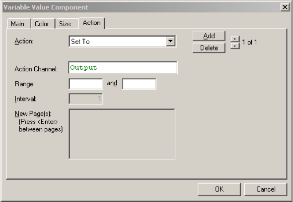
8) Leave the Range blank and click OK.
The range allows you to constrain the inputs to particular values. By leaving these properties blank, we are indicating that we do not want a range limitation. The page will now display your caption and either the most recent setting for Output, or a 0 with a big red X through it if you started from the last sample document. The red X indicates that Output does not have a valid value yet. This is because we haven't set it to anything.
9) Click on the component. A new window will appear requesting a new value. Enter a voltage value within the DAC range, such as 2, and click OK.
Output will now be set to the value you entered. The component will now display your new value without the big red X. If you tie a wire between DAC0 and AIN0 (on the U3-LV use DAC0 and FIO0) you will see the Pressure reading track with the DAC output, though multiplied by 100.
Note, if you’d like to be able to enter an output value in units other then volts, you need to create a Conversion and apply it to your output channel. We talked about conversions a little earlier. Conversions on output channels work in reverse. With regular input conversions, the formula is used to convert the devices units, usually volts, to your units. With output conversions, the formula is used to convert your units into the device units. So, if you had a variable pressure controller that controlled from 0 to 500 psi and took a 0 to 5V output, the conversion would be: Value / 100
Sample file: LJGuideSamples\AnalogOut.ctl
4.7 Toggling a digital output using a button
We talked a little about using a descriptive text component to toggle a digital output between its two states at the end of section 4.4. You can also create a button to toggle the output:
1) On a page, right click and select Buttons & Switches - Button.
2) Once the new component is on the screen, right click on it and select Properties....
3) For the Caption give whatever label you want
4) Click on the Action tab.
5) For Action, select Toggle Between from the drop down combobox.
6) For Action Channel type in the name of your digital output channel.
7) For Toggle Between, put 0 and 1. For digital outputs, only 0 and 1 apply, but you could also use this for toggling
an analog output between two voltages by specifying other values here.
8) Click OK
Now you can click on the button and your digital output channel will toggle between 0 and 1.
Sample file: LJGuideSamples\DescriptiveText.ctl