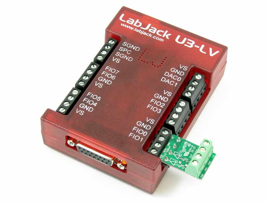
The LJTick-InBuff (LJTIB) is an input buffer tick that allows LabJack devices to directly measure pH sensors and other kinds of weak signals. Our main LabJack DAQ products (U3, U6, UE9, and T7) require somewhere on the order of 10 to 100pA of bias current. This accessory can really help users trying to measure signals with >10MΩ of source impedance. The LJTick-InBuff accomplishes this by adding a Texas Instruments OPA2140 high-precision, low-noise Op Amp in between a devices analog input channel and the sensor. Simply connect the LJTick-InBuff to a screw terminal with analog inputs and connect a sensor to the INA or INB screw terminal of the LJTick-InBuff.
-
1pA bias current
-
±10V input & output range
-
Has pads to optionally install gain resistors & input filter.
Common Applications
-
Measuring PH sensors.
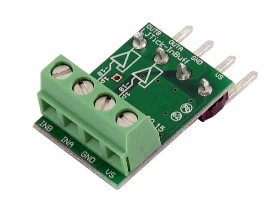
Screw Terminal Descriptions
VS: This is the same 5 volt output as the VS terminals on the LabJack itself. This is an output terminal, not an input. It can be used to provide 5 volt (nominal) power as needed.
GND: Same as LabJack ground (GND).
INA/INB: These input lines go through the Op Amps to have their signals amplified before being sent to a LabJack device.
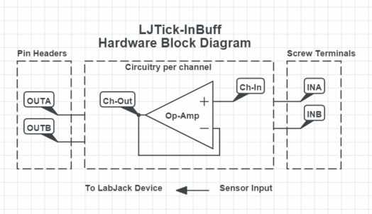
LJTick-InBuff Hardware Block Diagram
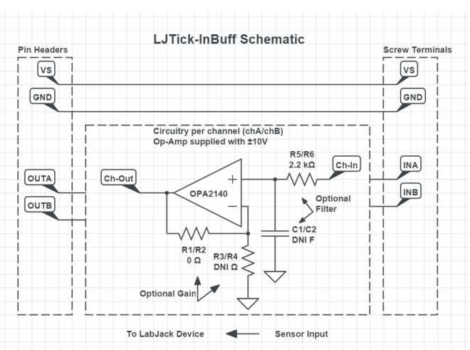
LJTick-InBuff Schematic
Usage with the T4 or U3-HV
The T4 and U3-HV have a mix of high voltage analog inputs (±10 volt range) and low voltage analog inputs (±2.5/2.4 volt range). Most input ticks are best used with the low voltage analog inputs, but the LJTick-InBuff is unique in that it has a ±10 volt output range and thus either type of analog input might be best depending on the range of the input signal.
Optional Gain and Filtering
The LJTick-InBuff is configured with unity gain (no amplification) and no filtering is applied at the inputs. The LJTick-InBuff has optional SMD pads to apply gain and filtering as shown in Figure 4.
Warning: Adding gain or filtering to the InBuff could modify circuit characteristics such as the input impedance, the frequency response, and noise sources. A good understanding of operational amplifiers is necessary to modify the LJTick-InBuff. Analog Devices and TI offer resources for operational amplifier and other linear design fundamentals:
https://www.analog.com/en/resources/technical-books/op-amp-applications-handbook.html
Voltage Gain
Resistors labeled R1/R2 and R3/R4 on the LJTick-InBuff can be modified to add gain to the InBuff operational amplifiers as described using Table 1 and the formulas below.
Gain = 1 + RF/RG
Vout = Vin * (1 + RF/RG)
Table 1. LJTick-InBuff Optional Gain Resistors
|
InBuff Channel Name |
InBuff Gain Resistor Part Label (RF) |
InBuff Gain Resistor Part Label (RG) |
|---|---|---|
|
INA |
R1 |
R3 |
|
INB |
R2 |
R4 |
Optional Low Pass Filter
Resistors labeled R5/R6 and capacitors labeled C1/C2 on the LJTick-InBuff can be modified to add a low pass filter to the inputs as described using Table 2 and the formulas below.
fcutoff = 1 / (2πRC)
Table 2. LJTick-InBuff Optional Filtering Parts
|
InBuff Channel Name |
InBuff Filter Resistor Part Label |
InBuff Filter Capacitor Part Label |
|---|---|---|
|
INA |
R5 |
C1 |
|
INB |
R6 |
C2 |
Specifications
|
Parameter |
Conditions |
Min |
Typical |
Max |
Units |
|
|
|
|
|
|
|
|
General |
|
|
|
|
|
|
Input Voltage Range |
|
-10 |
|
10 |
Volts |
|
Temperature Range |
|
-40 |
|
85 |
°C |
|
Supply Voltage |
|
4 |
|
5.25 |
Volts |
|
Supply Current |
|
|
28 |
|
mA |
|
|
|
|
|
|
|
|
Input Bias Current |
|
|
±0.5 |
±10 |
pA |
|
Input Impedance |
|
|
10^13 |
|
Ω |
|
Input Capacitance |
|
|
10 |
|
pF |
|
Gain Accuracy |
|
|
|
|
|
|
Offset Accuracy |
|
|
|
±100 |
μV |
|
Cutoff Frequency |
0-5V Input Sine Wave |
|
4.3 |
|
MHz |
|
|
±10V Input Sine Wave |
|
120 |
|
kHz |
For more specifications about the Op Amp used in the LJTick-InBuff refer to the Texas Instruments OPA2140 datasheet.
CAD