LJTick-RelayDriver Datasheet
The LJTick-RelayDriver (LJTRD) is a signal-conditioning module that allows two digital outputs to each control up to 50 volts and 200 mA. The 4-pin design plugs into the standard DIO/DIO/GND/VS screw terminal block found on newer LabJacks such as the U3 and UE9.
In a scenario requiring multiple LJTick-RelayDrivers, consider instead the PS12DC power switching board. It operates in a similar way, but has 12 channels, high side switching, and digital isolation.
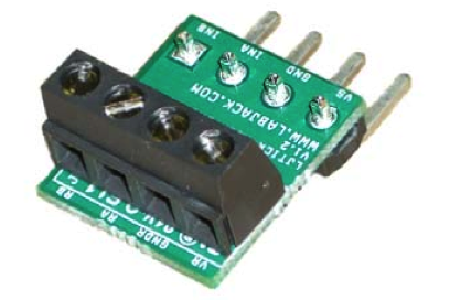
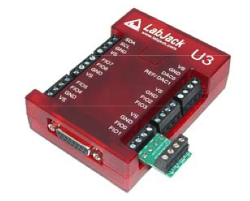
The pictures below show the LJTRD by itself and plugged in to a LabJack.
Extending from the back of the LJTRD are four pins. The first two pins provide +5 volt power and ground from the LabJack, although +5 volt power is not used by the LJTRD and thus is not connected to anything. The other two pins connect to digital I/O on the LabJack. The four pins plug directly into the 5.0 mm spaced screw terminals on the LabJack U3/UE9 as shown in Figure 2. The LJTRD should be plugged into a digital I/O block, as opposed to an analog I/O block.
The LJTRD has a 4-position screw-terminal providing the following connections:
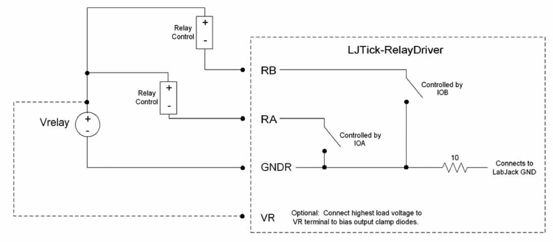
RA/RB: The high side of each output switch. When IOA/IOB from the LabJack is set to output-high, the respective switch is closed. When IOA/IOB is set to output-low or input, the respective switch is open. Each switch can hold off up to 50 volts and can sink up to 200 mA.
GNDR: The low side of both output switches. Connected to LabJack GND via a 22 ohm resistor (resistor is on the LJRTD).
VR: Connect the load voltage to this terminal to bias the internal clamping diodes on each switch. If each switch has a different load voltage, the highest voltage should be connected to VR. The clamping diodes help suppress switching transients, and can be particularly important when dealing with inductive loads such as mechanical relays or solenoids. Although this connection is optional, there is usually no reason not to use it.
When connecting a relay or other type of load, there will be a voltage drop depending on current. Below is a chart which represents the voltage drops that can be expected at various currents.
Table 3. Voltage drop based on current
Current (mA) | Voltage Drop (V) | |
|
|
|
| FIO | EIO/CIO |
200 | 3.29 | 1.05 |
150 | 2.55 | 0.98 |
100 | 2.17 | 0.91 |
50 | 1.55 | 0.83 |
If controlling at high frequencies, please note the following table. As current through the RelayDriver increases, the cutoff frequency also increases, which means that if you encounter problems controlling at high frequencies, the load resistance should be decreased to allow more current to flow through the RelayDriver. This behavior is almost never a problem when controlling relays, since relays typically draw 3 to 20mA, and the LabJack U3 will not output a PWM frequency exceeding 187kHz.
Table 4. Cutoff Frequency based on current
Current (mA) | Cutoff Frequency |
|
|
0.5 | 210kHz |
10.5 | 430kHz |
41.4 | 1.2MHz |
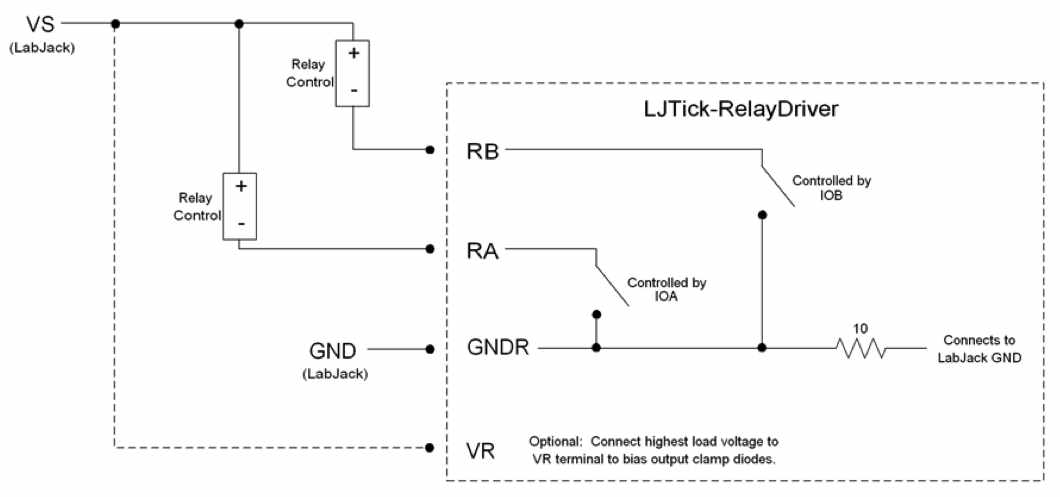
Following are two figures showing typical connections for the LJTRD. The first diagram shows the general connections, while the second is for the specific case where the LJTRD is controlling VS (5 volts) from the LabJack itself.

Figure 5: General Connection Diagram

Figure 6: Connection Diagram When Controlling VS from LabJack
Testing Basic Operation
Use the Dashboard in Kipling (T-series) or the Test panel in LJControlPanel to control the applicable DIO lines. The DIO have 3 states (i.e. tristate digital I/O):
Output-High: Active. The "switch" on the LJTRD is closed.
Output-Low: Disabled. The "switch" on the LJTRD is open.
Input: Disabled. The "switch" on the LJTRD is open.
If the "switch" mentioned above was mechanical you could simply put a DMM from RA to GNDR and measure resistance, but that generally does not work with solid-state switches. With a solid-state switch the best way to test is to connect as shown in Figure 6 but put in a resistor where it says "Relay Control". So for example, connect one side of a 1k resistor (100 to 1,000,000 should work) to any VS terminal (~5 volts), connect the other side to RA, and connect GNDR to any GND terminal. Now use your DMM to measure the voltage across the resistor. When the LJTRD is disabled the voltage will be 0 as no current is flowing so no voltage is dropping. When the LJTRD is active the voltage will be perhaps 3-5 volts (see Table 3 above).
CAD
Declaration of Conformity
Manufacturers Name: LabJack Corporation
Manufacturers Address: 6900 West Jefferson Ave Suite 110, Lakewood, CO 80235 USA
Declares that the product
Product Name: LabJack Tick Relay Driver
Model Number: LJTRD
conforms to the following Product Specifications:
EMC Directive: 89/336/EEC
EN 55011 Class A
EN 61326-1: General Requirements


