Common resistive sensors are thermistors and RTDs. There are four basic ways to measure resistance using a LabJack device:
-
Using a simple voltage divider
-
Using a buffered voltage divider
-
Using the LJTick-Resistance accessory
-
Using the 10UA and 200UA constant current sources (if available)
We recommend the LJTick-Resistance as the best option for LabJacks that support analog input tick accessories.
Basic Voltage Divider
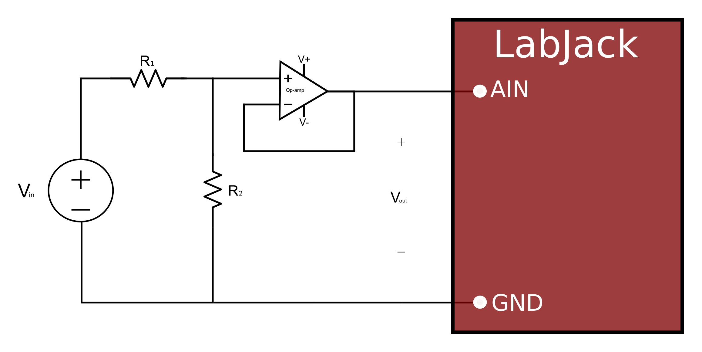
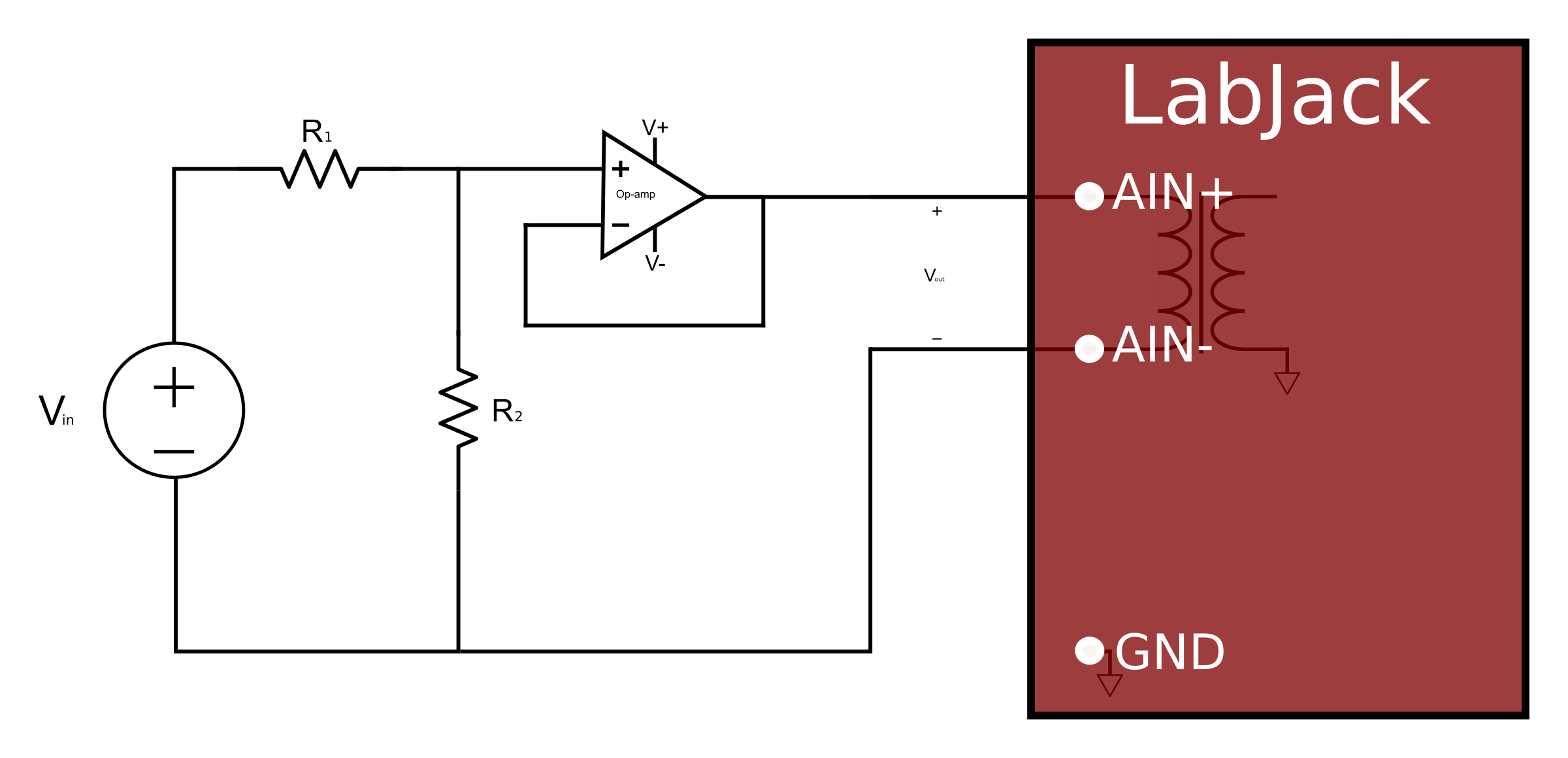
A common way to measure resistance is to build a voltage divider as shown in Figure 1a and Figure 1b, where one of the resistors is known and the other is the unknown. If Vin is known and Vout is measured, the voltage divider equation can be rearranged to solve for the unknown resistance.
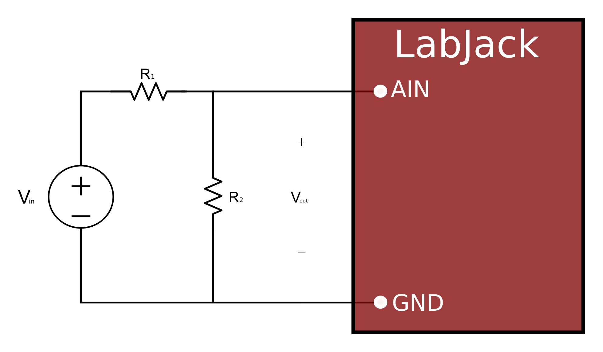
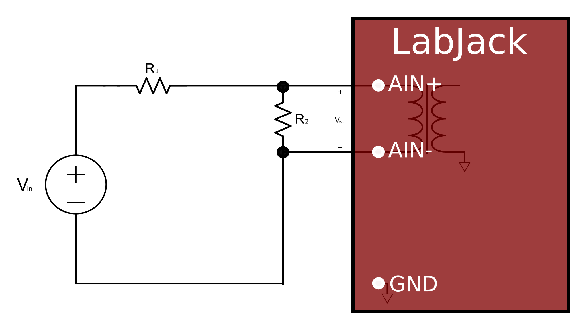
Voltage divider equation solved for R1:
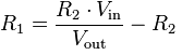
Solved for R2:
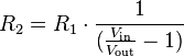
To measure resistance, put a known resistor value as (R1), the resistor to measure as (R2), and power it with a known voltage (Vin). Use the equation solved for R2 to get your resistance value. As a general recommendation, (R1 + R2) should remain greater than about 500Ω of resistance, so that the LabJack device doesn't have to sink too much current. Also, be sure to get a precision resistor with a good (<=25ppm) temperature coefficient as your known resistance value.
For non-isolated devices, the source voltage (Vin) must be referred to the same ground as the device (GND). If R1 is going to be very low, and Vin exceeds the measurement range of the analog input, then use a smaller Vin.
For devices with 2-terminal isolated analog inputs (only the T8 as of this writing), the "GND" connection shown in the figure above would actually be the negative analog input terminal (AIN#-).
Power Supply Options
Since the value of Vin affects the resistance measurement it is important to select a power supply with good accuracy and stability.
-
The LJTick-Vref can provide a stable 2.5 V or 4.096 V output.
-
The LJTick-Resistance provides a stable 2.5 V reference output. See the LJTick-Resistance section below.
-
If you have a T8, there are two 3.3 V Supply pins that provide a stable reference output.
Buffered Voltage Divider
When measuring higher resistance (generally above 10k), a buffer can be used. The following figure shows a resistive voltage divider followed by an op-amp configured as non-inverting unity-gain (i.e. a buffer).
The op-amp is chosen to have low input bias currents so that large resistors can be used in the voltage divider. For 0-5 volt applications, where the amp will be powered from Vs and GND, a good choice would be the OPA344 from Texas Instruments (ti.com). The OPA344 has a very small bias current that changes little across the entire voltage range. Note that when powering the amp from Vs and GND, the input and output to the op-amp is limited to that range, so if Vs is 4.8 volts your Vin should be 0-4.8 volts.
LJTick-Resistance
We recommend using the LJTick-Resistance with supported LabJack devices because it is a "buffered voltage divider" as described above. It includes a stable 2.5V reference.
Typical use is to connect Vref to one side of an unknown resistance (Ru), and connect the other side of Ru to IN on the LJTR. For best results on the U6/T7 you would also connect Vref to some analog input to measure the actual value. Then use the following equations to determine Ru:
Vout = Vref * R3 / (Ru + R3)
Ru = ((Vref - Vout) * R3) / Vout
R3 is the precision resistor to ground in the voltage divider circuit. The LJTick-Resistance is available in -1000, -10k, -100k, and -1M versions where those numbers are the value of R3. Choose the version where R3 is similar to the nominal or mid-range value of Ru.
Example: LJTick-Resistance-100k. Vref is connected through an unknown resistor Ru. Vref is measured as 2.50V and Vout is measured as 1.20V. That means Ru = (2.5-1.20)*100000/1.20 = 108333 ohms.
10UA and 200UA Current Sources
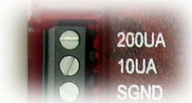
If you only need to measure a few resistance values, and your LabJack device has the 10UA and 200UA current source terminals, this is a good option.
The actual value of each current source is noted during factory calibration and stored with the calibration constants on the device. These can be viewed using the device info tab of Kipling (for T-series devices) or the test panel in LJControlPanel (for UD devices). Note that these are fixed constants stored during calibration, not a real time current readings.
The current sources have good accuracy and temperature coefficient, but for improvement a fixed resistor can be used as one of the resistors in the figures below. The Y1453-100 and Y1453-1.0K from Digikey have excellent accuracy and very low tempco. By measuring the voltage across one of these you can calculate the actual current at any time.
The current sources can drive about 3 volts max, thus limiting the maximum load resistance to about 300 kΩ (10UA) and 15 kΩ (200UA).
Multiple resistances can be measured by putting them in series and measuring the voltage across each. Some applications might need to use differential inputs to measure the voltage across each resistor, but for many applications it works just as well to measure the single-ended voltage at the top of each resistor and subtract in software.
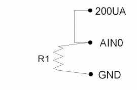
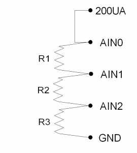
Figure 4 shows a simple setup measuring 1 resistor. If R1=3k, the voltage at AIN0 will be 0.6 volts.
Figure 5 shows a setup to measure 3 resistors using single-ended analog inputs. If R1=R2=R3=3k, the voltages at AIN0/AIN1/AIN2 will be 1.8/1.2/0.6 volts. That means AIN0 and AIN1 would be measured with the +/-10 volt range, while AIN2 could be measured with the +/-1 volt range. This points out a potential advantage to differential measurements, as the differential voltage across R1 and R2 could be measured with the +/-1 volt range, providing better resolution.
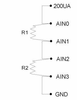
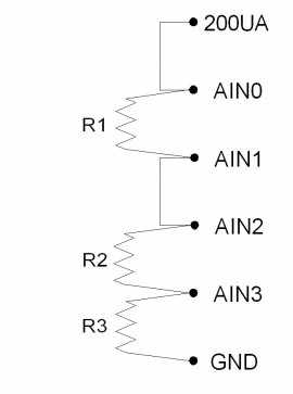
Figure 6 shows a setup to measure 2 resistors using differential analog inputs. AIN3 is wasted in this case, because it is connected to ground, so a differential measurement of AIN2-AIN3 is the same as a single-ended measurement of AIN2. That leads to Figure 7, which shows R1 and R2 measured differentially and R3 measured single-ended.