Overview By Device
*The accuracy specs in this section relate to the sensor measuring the temperature of itself, and include error due to the linear equation fit. At a given time the sensor might be at a different temperature than other parts of the device.
T4
Sensor Range: -50°C to 150°C
T4 Operating Range: -40°C to 85°C
Accuracy (20°C to 40°C): ±1.5°C*
Accuracy (-20°C to 50°C): ±2.0°C*
Accuracy (-45°C to 85°C): ±3.5°C*

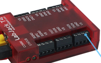
The T4 has an LM94021 temperature sensor (with GS=10) connected to an internal analog input. The sensor is physically located on the top of the PCB behind the VS screw terminal of the FIO4 and FIO5 screw terminal block.
T7
Sensor Range: -50°C to 150°C
T7 Operating Range: -40°C to 85°C
Accuracy (20°C to 40°C): ±1.5°C*
Accuracy (-20°C to 50°C): ±2.0°C*
Accuracy (-45°C to 85°C): ±3.5°C*
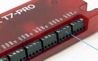
The T7 has an LM94021 temperature sensor (with GS=10) connected to internal analog input channel 14 (AIN14). The sensor is physically located on the bottom of the PCB between the AIN0/1 and AIN2/3 screw-terminals.
T8
Sensor Range: -50°C to 150°C
T8 Operating Range: -40°C to 85°C
Accuracy (20°C to 40°C): ±1.5°C*
Accuracy (-20°C to 50°C): ±2.0°C*
Accuracy (-45°C to 85°C): ±3.5°C*

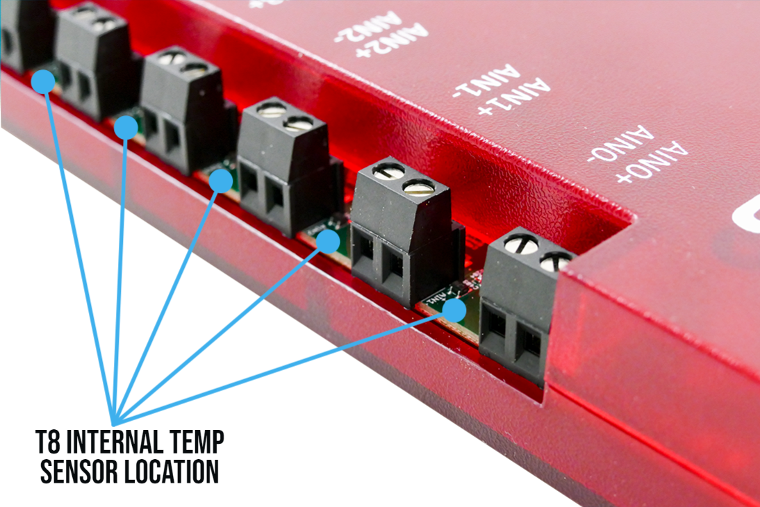
The T8 has LM94021 temperature sensors (with GS=01) near the screw terminals of each analog input. The thermal transfer between different screw terminals is reduced by the channel-to-channel isolation design of the T8, and thus it is more likely that different screw terminals can be at different temperatures.
Device Temperature
Read TEMPERATURE_DEVICE_K to get the device temperature. This is the temperature of the internal temperature sensor itself.
Air Temperature
TEMPERATURE_AIR_K is an estimate of the ambient air temperature outside the device:
It is calculated depending on whether Ethernet and/or WiFi is enabled as follows:
-
USB
TEMPERATURE_AIR_K = TEMPERATURE_DEVICE_K - 4.3 -
USB & Ethernet
TEMPERATURE_AIR_K = TEMPERATURE_DEVICE_K - 4.9 -
USB & WiFi
TEMPERATURE_AIR_K = TEMPERATURE_DEVICE_K - 4.9 -
USB & Ethernet & WiFi
TEMPERATURE_AIR_K = TEMPERATURE_DEVICE_K - 5.5
These offsets were determined from measurements with the enclosure on and in still air. We noted that the time constant was about 12 minutes, meaning that 12 minutes after a step change you are 63% of the way to the new value.
Timing
T4: TEMPERATURE_AIR_K and TEMPERATURE_DEVICE_K always use ResolutionIndex=5. Which means they take about 0.8 ms per reading.
T7 / T7-Pro: TEMPERATURE_AIR_K and TEMPERATURE_DEVICE_K always use Range = 10 and ResolutionIndex=8. Which means they take about 1.09 ms per reading from Table A.3.1.1.
T8: Measurement time will vary base on the current settings of the analog system and which register the reading is being requested from. TEMPERATURE#(0:8) will run a new measurement at the current rate and resolution settings of the analog system. Reading from TEMPERATURE#(0:8)_CAPTURE will return the most recently captured value. Reading the captured value is very fast, on the order of a couple microseconds. The communication overhead and any other registers being read will dominate the command-response time.
Due to a hardware limitation, the maximum sampling rate of the T8 temperature sensors is 250 Hz and will return readings of -9999 if the sampling rate is higher than 250 Hz. The register AIN_SAMPLING_RATE_HZ controls the sampling rate of all T8 temperature sensors and analog inputs. See section 14.0 Analog Inputs for additional information about AIN_SAMPLING_RATE_HZ.
Extra T7 Details
As an alternative to reading TEMPERATURE_DEVICE_K or TEMPERATURE_AIR_K, a read of AIN14 returns the raw voltage of the internal temperature sensor, which can be converted to device temperature using the following:
Device temperature K = volts * -92.6 + 467.6
You can read the raw temp sensor voltage from AIN14 in stream mode, but cannot read TEMPERATURE_DEVICE_K or TEMPERATURE_AIR_K since the internal math that is required for them is too slow. If streaming, use AIN14 to get volts and use the above formula to get device temperature in K. For an estimate of air temperature see the "Air Temperature" section above.
Extra T8 Details
The T8 has 8 internal temperature sensors. One next to each AIN screw terminal. All the temperature sensors are measured simultaneously along with the analog inputs, and the results are stored in capture registers for later reading.
The normal registers, TEMPERATURE_DEVICE_K and TEMPERATURE_AIR_K, will report the value from TEMPERATURE0, the AIN0 temperature sensor.
Note on Thermocouples
The value from TEMPERATURE_DEVICE_K best reflects the temperature of the built-in screw-terminals AIN0-AIN3, so use that for cold junction compensation (CJC) if thermocouples are connected there.
The internal sensor has a specified accuracy of ±2.0 °C across the range of -20 to +50 °C. Allowing for a slight difference between the sensor temperature and the temperature of the screw-terminals, expect the returned value minus 3 °C to reflect the temperature of the built-in screw-terminals with an accuracy of ±2.5 °C.
If thermocouples are connected to the CB37, you want to know the temperature of the screw-terminals on the CB37. The CB37 is typically at the same temperature as ambient air, so use the value from register TEMPERATURE_AIR_K for CJC. Better yet, add a sensor such as the LM34CAZ to an unused analog input on the CB37 to measure the actual temperature of the CB37.
If thermocouples are connected to an LJTick-Amp (typical with the T4), you want to know the temperature of the screw-terminals on the LJTIA, which we would expect to be close to ambient, so use the value from register TEMPERATURE_AIR_K for CJC.

