High Current Output
The DACs on the U3 can output quite a bit of current, but they have 50 Ω of source impedance that will cause voltage drop. To avoid this voltage drop, an op-amp can be used to buffer the output, such as the non-inverting configuration shown in Figure 2-3. A simple RC filter can be added between the DAC output and the amp input for further noise reduction. Note that the ability of the amp to source/sink current near the power rails must still be considered. A possible op-amp choice would be the TLV246x family (ti.com).
Different Output Ranges
See the end of this section for information about the LJTick-DAC which has a +/-10V range.
The typical output range of the DACs is about 0.04 to 4.95 volts. For other unipolar ranges, an op-amp in the non-inverting configuration (Figure 2.6-1) can be used to provide the desired gain. For example, to increase the maximum output from 4.95 volts to 10.0 volts, a gain of 2.02 is required. If R2 (in Figure 2-3) is chosen as 100 kΩ, then an R1 of 97.6 kΩ is the closest 1% resistor that provides a gain greater than 2.02. The +V supply for the op-amp would have to be greater than 10 volts.
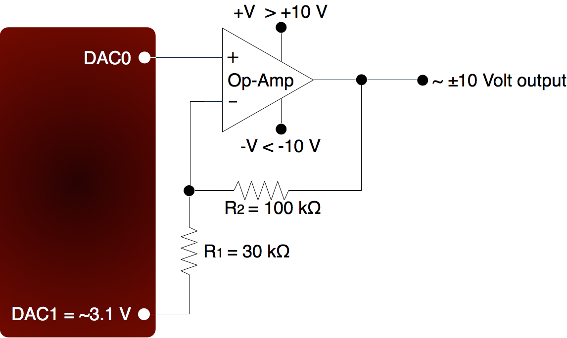
For bipolar output ranges, such as ±10 volts, a similar op-amp circuit can be used to provide gain and offset, but of course the op-amp must be powered with supplies greater than the desired output range (depending on the ability of the op-amp to drive it’s outputs close to the power rails). If ±10, ±12, or ±15 volt supplies are available, consider using the LT1490A op-amp (linear.com), which can handle a supply span up to 44 volts.
A reference voltage is also required to provide the offset. In the following circuit, DAC1 is used to provide a reference voltage. The actual value of DAC1 can be adjusted such that the circuit output is 0 volts at the DAC0 mid-scale voltage, and the value of R1 can be adjusted to get the desired gain. A fixed reference (such as 2.5 volts) could also be used instead of DAC1.
A two-point calibration should be done to determine the exact input/output relationship of this circuit. Refer to application note SLOA097 from ti.com for further information about gain and offset design with op-amps.
LJTick-DAC
There is an accessory available from LabJack called the LJTick-DAC that provides a pair of 14-bit analog outputs with a range of ±10 volts. The LJTick-DAC plugs into any digital I/O block, and thus up to 10 of these can be used per U3 to add 20 analog outputs. The LJTick-DAC has various improvements compared to the built-in DACs on the U3:
-
Range of +10.0 to -10.0 volts.
-
Resolution of 14-bits.
-
Slew rate of 0.1 V/μs.
-
Based on a reference, rather than regulator, so more accurate and stable.
-
Does not affect analog inputs in any configuration.
App Notes
See our Analog Output app notes for additional relevant information.