Hardware Variants
The U6 is available in a few different variants.
-
U3-LV - This is the normal version in a red enclosure.
-
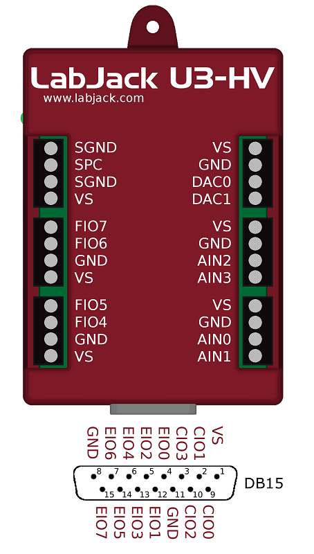
U3-HV - Same as the U3-LV, with the exception that the first four FIO are replaced by analog inputs which have ±10 V input range.
-
U3-LV-OEM - Same as U3-LV, but does not include an enclosure, most external connection components such as screw terminals are not included. Full details can be found here: OEM Details.
-
U3-HV-OEM -Same as U3-HV, but does not include an enclosure, most external connection components such as screw terminals are not included. Full details can be found here: OEM Details.
IO Summary
The U3 has 3 different I/O areas:
-
Communication Edge,
-
Screw Terminal Edge,
-
DB Edge.
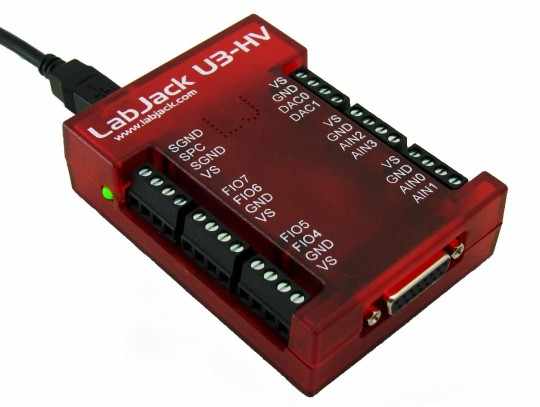
The communication edge has a USB type B connector (with black cable connected in Figure 2-1). All power and communication is handled by the USB interface.
The screw terminal edge has convenient connections for the analog outputs and 8 flexible I/O (digital I/O, analog inputs, timers, or counters). The screw terminals are arranged in blocks of 4, with each block consisting of Vs, GND, and two I/O. There is also a status LED located on the left edge.
The DB Edge has a D-sub type connectors called DB15 which has the 8 EIO lines and 4 CIO lines. The EIO lines are flexible like the FIO lines, while the CIO are dedicated digital I/O.
Subsections
-
2.1 - USB [U3 Datasheet] -
2.2 - Status LED [U3 Datasheet] -
2.3 - GND and SGND [U3 Datasheet] -
2.4 - VS [U3 Datasheet] -
2.5 - Flexible I/O (FIO/EIO) [U3 Datasheet] -
2.6 - AIN [U3 Datasheet] -
2.7 - DAC [U3 Datasheet] -
2.8 - Digital I/O [U3 Datasheet] -
2.9 - Timers/Counters [U3 Datasheet] -
2.10 - SPC (… and SCL/SDA/SCA) [U3 Datasheet] -
2.11 - DB15 [U3 Datasheet] -
2.12 - U3-OEM [U3 Datasheet] -
2.13 - Hardware Revision Notes [U3 Datasheet]