STATUS - The Green LED
The green STATUS LED indicates when the device is performing autonomous tasks or is in a special operational state. It follows these specific blinking patterns:
-
Streaming: Blinks continuously while a stream is active.
-
Lua Scripting: Blinks once whenever a running Lua script accesses a Modbus register.
-
T8 Recovery Mode: Blinks twice every 2 seconds (specific to the T8).
-
Communication Activity: Operates in conjunction with the POWER/COMM LED to indicate traffic or system states (see the Combined LED Activity section below).
-
Combined Activity: Operates in conjunction with the COMM LED to indicate internal processes or error states (see the Combined LED Activity section).
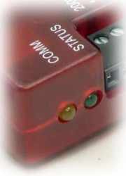
COMM - The Yellow LED
The primary purpose of the yellow COMM LED is to indicate data packet transfers between the LabJack and the host computer. It follows these specific blinking patterns:
-
Packet Transfer: Blinks once per packet. To remain visible during high-speed communication, the LED is limited to a 10 Hz blink rate, even if the actual transfer rate exceeds 10 packets per second.
-
Stream Mode: Blinks continuously while a stream is active.
-
USB Enumeration: Blinks a few times immediately after successfully connecting to a USB host.
-
Combined Activity: Operates in conjunction with the STATUS LED to indicate internal processes or error states (see the Combined LED Activity section).
Combined LED Activity
In certain states, both LEDs will blink in patterns to indicate specific internal processes or error conditions.
-
Blinking in Unison: The device is currently computing checksums. This is typical during startup or memory operations.
-
Alternating Blinks: The device is copying a firmware image. Do not disconnect power or communication during this process.
-
Triple Blinks (Both LEDs): The device has encountered a hardware error.
-
Action: Try power-cycling the device. If the pattern persists, contact LabJack support.
-
Normal Behavior
Use these three common scenarios to verify that your T-series device is functioning correctly.
1. Power-Up Sequence
-
Initial Reset: Both LEDs blink rapidly for approximately 1 second.
-
Boot Completion: The COMM LED turns off and the STATUS LED remains solid on.
-
USB Enumeration: If connected to a host, the COMM LED will blink a few times and then remain solid on.
2. Idle State
-
The STATUS LED should be solid on with no blinking. If connected over USB, the COMM LED will be solid on as well. This indicates the device is powered, enumerated, and waiting for commands.
3. While Viewing Kipling’s Dashboard
-
STATUS (Green): Solid on.
-
COMM (Yellow): Solid on, but with a quick double-blink once per second. This blink indicates the active communication "heartbeat" between the Kipling software and the device.
Troubleshooting
If your LED behavior does not match the normal patterns described above, follow these steps in order. If the device begins functioning normally at any stage, you do not need to continue.
-
Check LED Mode (Software Settings) The LEDs may have been intentionally disabled or set to manual control.
-
Attempt to connect to the device using Kipling.
-
If it connects, use the Register Matrix to check the values of
POWER_LEDandPOWER_LED_DEFAULT. -
If the value is anything other than 1, the LEDs are in a special mode. Change them back to 1 to restore default behavior.
-
-
Perform a Factory Reset If software settings are not the cause, you can reset the device to its out-of-the-box configuration using the hardware jumper.
-
Follow the SPC Jumper Procedure detailed in Section 11.0 SPC of the [T-Series Datasheet].
-
-
Enter Recovery (Emergency) Mode If the device is unresponsive, you can force it into a basic bootloader state.
-
Use the jumper procedure to boot into Recovery Mode.
-
If the device is detected by Kipling in this mode, perform a Firmware Update to restore normal operation.
-
-
Further Support If the LEDs remain off or abnormal after the steps above, refer to our guide on USB Communication Failure.
LED Configuration
The LED mode can be set using the following registers: