P1, P2, and P3 are basically just 3 alternate ways to connect the PS12DC.
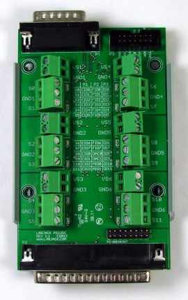
P1 - DB15 connector (top left): Mates to small and large LabJacks, like a U3
P2 - DB37 connector (bottom): Mates to only larger LabJack models, like a U6
P3 - 14 pin header (top right): Can be used to wire the board to any other digital output source, like an Arduino.
P2-BREAKOUT - 16 pin header (bottom): For access to covered-up analog inputs when the PS12DC is connected to a LabJack via P2.
When connected to a LabJack, or other digital output source, the name of the output can be determined by looking at the chart below.
Table C1. Channel output and PSU input based on switch number
|
Switch # |
P1 |
P2 |
P3 |
Power Supply In |
|
|
|
|
|
|
|
S0 |
EIO0 |
FIO0 |
DI0 |
VS1 GND1 |
|
S1 |
EIO1 |
FIO1 |
DI1 |
|
|
S2 |
EIO2 |
FIO2 |
DI2 |
VS2 GND2 |
|
S3 |
EIO3 |
FIO3 |
DI3 |
|
|
S4 |
EIO4 |
FIO4 |
DI4 |
VS3 GND3 |
|
S5 |
EIO5 |
FIO5 |
DI5 |
|
|
S6 |
EIO6 |
FIO6 |
DI6 |
VS4 GND4 |
|
S7 |
EIO7 |
FIO7 |
DI7 |
|
|
S8 |
CIO0 |
DAC0 |
DI8 |
VS5 GND5 |
|
S9 |
CIO1 |
DAC1 |
DI9 |
|
|
S10 |
CIO2 |
MIO0 |
DI10 |
VS6 GND6 |
|
S11 |
CIO3 |
MIO1 |
DI11 |
Table C2. P2 breakout
|
Pin |
Analog Input |
|
|
|
|
1 |
AGND |
|
2 |
AIN0 |
|
3 |
AIN1 |
|
4 |
AIN2 |
|
5 |
AIN3 |
|
6 |
AIN4 |
|
7 |
AIN5 |
|
8 |
AIN6 |
|
9 |
AIN7 |
|
10 |
AIN8 |
|
11 |
AIN9 |
|
12 |
AIN10 |
|
13 |
AIN11 |
|
14 |
AIN12 |
|
15 |
AIN13 |
|
16 |
AGND |
Example: Connect the PS12DC via the 15-pin D-Sub connector on a LabJack U3. You desire to toggle power to switch S9, so you locate the appropriate connector in-use, which is P1, and then follow the row for S9, which points to CIO1. This means that changing CIO1 from output-low to output-high will change the S9 terminal from 0V to whatever voltage is connected to VS5 and GND5.
Detailed pin-out
The detailed pin-out information below is for advanced users. It may be useful to people making a custom board that mates with the OEM PS12DC, or someone who needs to use the rails VM+ and VM- in addition to a PS12DC that is connected on P2. Most users need not concern themselves with this section.
Table C3. Detailed pin-out information for all connectors on PS12
|
P1 |
|
P3 |
|
P2 |
|
J2 (OEM) |
||||
|
Pin |
Connection |
|
Pin |
Connection |
|
Pin |
Connection |
|
Pin |
Connection |
|
|
|
|
|
|
|
|
|
|
|
|
|
1 |
VS |
|
1 |
GND |
|
1 |
GND |
|
1 |
GND |
|
2 |
S9 |
|
2 |
S11 |
|
2 |
PIN2 |
|
2 |
GND |
|
3 |
S11 |
|
3 |
S10 |
|
3 |
S6 |
|
3 |
PIN20 |
|
4 |
S0 |
|
4 |
S9 |
|
4 |
S4 |
|
4 |
PIN2 |
|
5 |
S2 |
|
5 |
S8 |
|
5 |
S2 |
|
5 |
S7 |
|
6 |
S4 |
|
6 |
S7 |
|
6 |
S0 |
|
6 |
S6 |
|
7 |
S6 |
|
7 |
S6 |
|
7 |
S11 |
|
7 |
S5 |
|
8 |
GND |
|
8 |
S5 |
|
8 |
GND |
|
8 |
S4 |
|
9 |
S8 |
|
9 |
S4 |
|
9 |
VM- |
|
9 |
S3 |
|
10 |
S10 |
|
10 |
S3 |
|
10 |
GND |
|
10 |
S2 |
|
11 |
GND |
|
11 |
S2 |
|
11 |
S8 |
|
11 |
S1 |
|
12 |
S1 |
|
12 |
S1 |
|
12 |
AIN13 |
|
12 |
S0 |
|
13 |
S3 |
|
13 |
S0 |
|
13 |
AIN11 |
|
13 |
S10 |
|
14 |
S5 |
|
14 |
GND |
|
14 |
AIN9 |
|
14 |
S11 |
|
15 |
S7 |
|
|
|
|
15 |
AIN7 |
|
15 |
MIO2 |
|
|
|
|
|
|
|
16 |
AIN5 |
|
16 |
GND |
|
J1 (OEM) |
|
|
|
|
17 |
AIN3 |
|
17 |
VS |
|
|
Pin |
Connection |
|
|
|
|
18 |
AIN1 |
|
18 |
VM- |
|
1 |
GND |
|
|
|
|
19 |
AGND |
|
19 |
VM+ |
|
2 |
VS |
|
|
|
|
20 |
PIN20 |
|
20 |
GND |
|
3 |
S8 |
|
|
|
|
21 |
S7 |
|
21 |
S8 |
|
4 |
S9 |
|
|
|
|
22 |
S5 |
|
22 |
S9 |
|
5 |
S10 |
|
|
|
|
23 |
S3 |
|
23 |
AGND |
|
6 |
S11 |
|
|
|
|
24 |
S1 |
|
24 |
AIN13 |
|
7 |
GND |
|
|
|
|
25 |
S10 |
|
25 |
AIN12 |
|
8 |
S0 |
|
|
|
|
26 |
MIO2 |
|
26 |
AIN11 |
|
9 |
S1 |
|
|
|
|
27 |
VS |
|
27 |
AIN10 |
|
10 |
S2 |
|
|
|
|
28 |
VM+ |
|
28 |
AIN9 |
|
11 |
S3 |
|
|
|
|
29 |
S9 |
|
29 |
AIN8 |
|
12 |
S4 |
|
|
|
|
30 |
AGND |
|
30 |
AIN7 |
|
13 |
S5 |
|
|
|
|
31 |
AIN12 |
|
31 |
AIN6 |
|
14 |
S6 |
|
|
|
|
32 |
AIN10 |
|
32 |
AIN5 |
|
15 |
S7 |
|
|
|
|
33 |
AIN8 |
|
33 |
AIN4 |
|
16 |
GND |
|
|
|
|
34 |
AIN6 |
|
34 |
AIN3 |
|
|
|
|
|
|
|
35 |
AIN4 |
|
35 |
AIN2 |
|
|
|
|
|
|
|
36 |
AIN2 |
|
36 |
AIN1 |
|
|
|
|
|
|
|
37 |
AIN0 |
|
37 |
0 |
|
|
|
|
|
|
|
|
|
|
38 |
GND |
|
|
|
|
|
|
|
|
|
|
39 |
GND |
|
|
|
|
|
|
|
|
|
|
40 |
AGND |