PS12DC Datasheet Overview
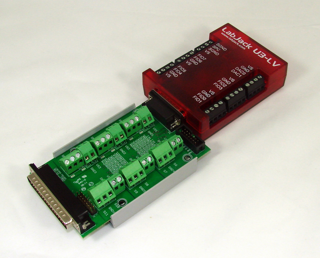
The PS12DC is a power switching board designed for medium to low current DC power switching applications. Controlled through 12 digital outputs, the board can switch power sources ranging from 5 to 28V DC. Attach the PS12DC to the DB15 connector present on all compatible devices (all LabJack devices except the U12), and toggle the states of the EIO and CIO digital output lines to turn the switches on/off. This device requires at least one compatible power supply, and a multi-channel digital output source, such as a LabJack, or Arduino.
Features
-
12 digitally controlled switches with LED indicators
-
Optical isolation
-
Handles 5 - 28 Volt supply
-
Up to 750mA/chan
-
Thermal (self-resetting) fuse protection
-
Flyback protection
-
Snaptrack/DIN-rail compatible, with TE Connectivity P/N TKAD
Compatible Devices
Typical Applications
-
Solenoid Valves/Actuators
-
Relays
-
Simple DC Motors*
-
Horns/Bells/Alarms
-
Blowers/Fans
-
Low Voltage DC Lighting
-
LED Drivers
*If using a larger DC motor (above 12V DC, or bigger than 1" diameter as a general rule), we recommend installing supplementary snubber diodes, and inrush limiters, as large flyback and inrush currents can overwhelm the protection circuitry on the PS12DC, resulting in damage. Basically just buy a few of these $0.80 parts, and put one in series with each motor. See the end of Appendix D for details.
Subsections
How To Use
You will need a LabJack, a PS12DC, and something to control. The diagram below demonstrates how to make connections for controlling a DC motor, and a fan.
-
Option A - Items are powered by 5V power supply (VS) located on the LabJack, this is the most basic connection.
-
Option B - Items are powered by 12V external power supply.
-
More Options - See Appendix A - Wiring Diagrams
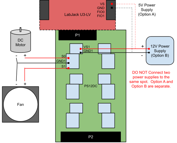
Once the wires are attached, turn the DC Motor on and off by toggling the state of the appropriate digital control line. When the control IO is output-low, S0 will sit at 0V. When the control IO is output-high, S0 will be at the voltage connected to VS1. Look at the IO Reference table below to identify which control line to toggle. The DC motor is connected to S0, so that means a state change in EIO0 will turn it on and off.
Table 1. Digital I/O pins for each switch
|
Switch # |
Digital IO |
|
S0 |
EIO0 |
|
S1 |
EIO1 |
|
S2 |
EIO2 |
|
S3 |
EIO3 |
|
S4 |
EIO4 |
|
S5 |
EIO5 |
|
S6 |
EIO6 |
|
S7 |
EIO7 |
|
S8 |
CIO0 |
|
S9 |
CIO1 |
|
S10 |
CIO2 |
|
S11 |
CIO3 |
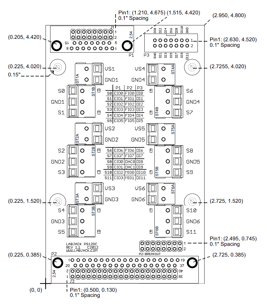
If the PS12DC is attached to the LabJack differently than in the picture above, there will be a different corresponding digital IO line. The full pinout details can be seen in Appendix C - Pinout Info .
Download LJControlPanel (for UD-series devices) or Kipling (for T-series devices) to get started, or create a program in one of our supported languages to communicate with the LabJack. It will also be necessary to install the device driver, the UD driver for the UD-series or the LJM driver for the T-series, so that the LabJack is recognized over USB.
Other Compatible Devices
Connect a PS12DC to any device with 3.3V to 5V digital outputs through the use of the P3 pin header. This includes Arduino, homemade boards, PCI DAQ boards, etc. Please note that when using other digital output boards, support is limited to the PS12DC. The image below shows an example of how to connect a PS12DC to an Arduino.
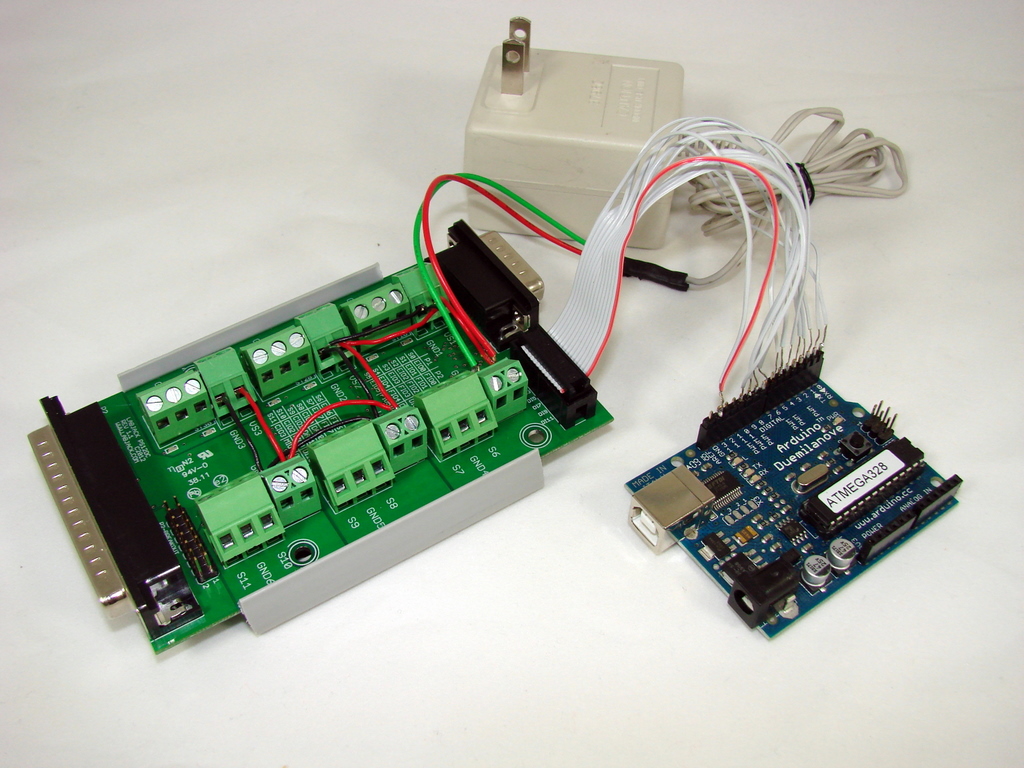
The Arduino, the Duemilanove model in our example, has 14 digital IO pins, the first 12 are connected to the PS12DC, and the two GND wires on the PS12DC are tied to GND on the Arduino.
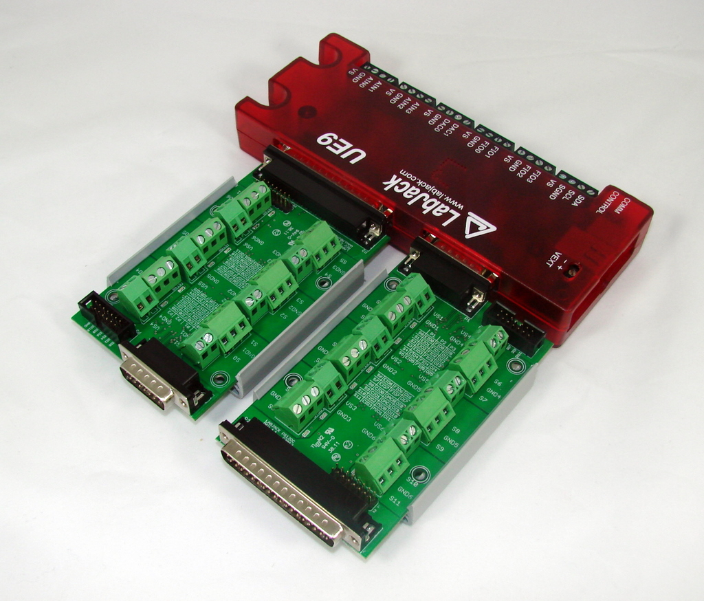
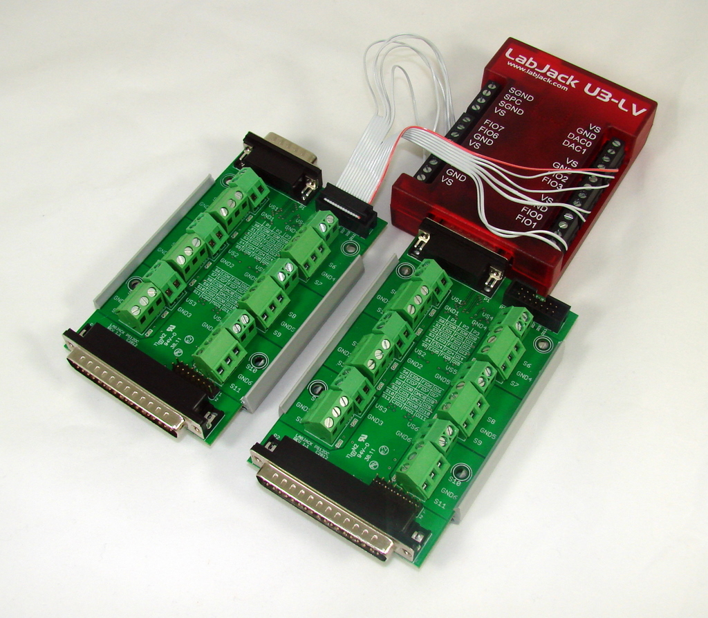
Multiple PS12DC boards can be connected to a single compatible LabJack, as shown in the image below. See Appendix B - Connection Options for more information.
Troubleshooting
If there are problems with the PS12DC, ensure the following:
-
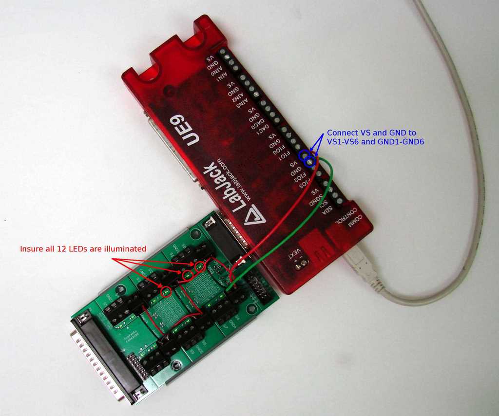
There is a working power supply (5 to 28V) connected to one of the power supply blocks, e.g. VS1/GND1. Connect wires to VS as shown below if no power supply is available.
-
The switch number under inspection is being powered. For instance, if checking S8, verify that VS5/GND5 are connected to a working power supply.
-
Verify that the LEDs turn on and off when the digital output states on the LabJack are toggled high and low. This can be accomplished by opening LJControlPanel (for U3, U6, or UE9) or Kipling (for T4, T7, or T8), and checking/un-checking the boxes next to the digital output of interest[1]. Or download the test program (U3, U6, or UE9 only): LJTestPS12DC.zip
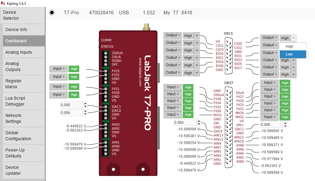
[1] To test operation of the PS12DC on T-series devices navigate to the Dashboard tab of Kipling; the Register Matrix is less useful for testing the PS12DC compared to the dashboard. From the Dashboard tab set the IO of interest (See the pinout info page) to "Output" and toggle the High/Low selection . When set "High" the LED next to the corresponding switch on the PS12DC should light up.
SnapTrack Specifications:
Description:
Non-Conductive, Extruded PVC Channel for mounting assemblies and printed circuit boards.
Flammability:
UL94: V-0
Environmental:
Maximum Service Temperature, Air: 163º F / 73º C
RoHS:
Complies with European Union Directive 2002/95/EC Restriction on Hazardous Substances
See the SnapTrack datasheet for more information:
https://www.scidyne.com/ftp/brochure/snaptrack.pdf
Drawings and CAD models
