Summary
The PS12DC can be connected several ways, the most common is through the DB15 connector. The following sections explain how to connect the board by using the extra connectors, and details about using multiple PS12DC at a time.
Single PS12DC
The PS12DC can be connected according to any of the following figures. All 12 switches will be operational, and their corresponding digital control lines can be referenced in Appendix C - Pinout Info.
Two PS12DC
This section explains how to connect a second PS12DC to each LabJack device, and the number of additional channels provided. It is assumed that the first PS12DC is connected to a LabJack through the DB15 connector.
-
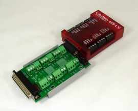
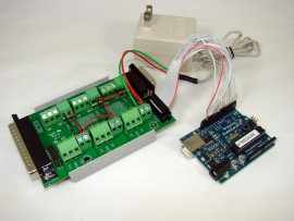
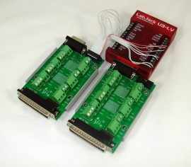
U3-LV: (10 addtl. switches) Connect a second PS12DC to the U3-LV by wiring the P3 header to the screw terminals. A ribbon cable with a rectangular connector is recommended for the task. Attach the female connector to the board, and splice the wires for the screw terminals on the U3-LV. DI0-DI7 would be wired to FIO0-FIO7, and two of the remaining digital input lines (DI8, DI9) can be connected to DAC0 and DAC1. Connect the two GND pins to GND on the U3.
-
Something like NKK Switches part number ISDCB812 (12 inch), or ISDCB824 (24 inch) would work, but anything with at least 14 positions, and 0.1" spacing should do the job. It also works to combine a 2x7 14-pin dual row IDC socket with some rainbow ribbon cable, if you prefer to assemble the cable yourself.
-
U3-HV:(6 addtl. switches) This is the same as the U3-LV, with the exception of the first 4 FIO channels; Since they are dedicated analog inputs, the U3-HV will limit the second PS12DC to only 6 extra channels, instead of the 10 possible for the U3-LV.
-
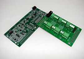
U6, U6-Pro:(10 addtl. switches)[1][2] Connect the second PS12DC to the U6 via the P2 connector. Reference the silkscreen table for corresponding digital lines.
-
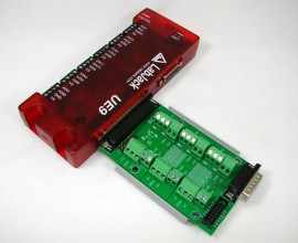
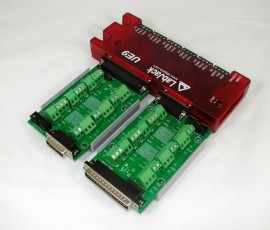
UE9, UE9-Pro: (12 addtl. switches)[1] Connect the second PS12DC to the UE9 via the P2 connector. Reference the silkscreen table for corresponding digital lines.
-
T7, T7-Pro: (12 addtl. switches)[1] Connect the second PS12DC to the T7 via the P2 connector. Reference the silkscreen table for corresponding digital lines.
[1]When connected to the DB37 connector on either the U6 or UE9, some of the analog inputs are covered up. To address the problem, those analog inputs re-appear on the PS12DC, under the P2-BREAKOUT header. Reference Appendix C - Pinout Info for details.
[2]The U6 shares CIO0, CIO1, and CIO2 with MIO0, MIO1, and MIO2. They are merely different names for the same digital channels. This causes some interesting behavior when two PS12DC are connected to a U6, since a state toggle in a CIO line will effect both boards. Switch S8 on P1 will toggle at the same time as S10 on P2 . Also S9 on P1 will toggle at the same time as S11 on P2. Because of this overlap, there are really only 10 unique channels provided by the second PS12DC, when connected to a U6.
OEM Capability
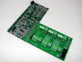
Connect an OEM PS12DC to an OEM LabJack by soldering a 0.1" spacing pin header to the LabJack, and then the OEM pin header holes on the PS12DC. Either J1 or J2 would work. LabJack does not stock the OEM version, but it is possible to contact us and place a custom order. The image below shows a possible configuration for a custom PS12DC.
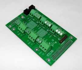
OEM PS12DC boards are useful for direct solder applications, when the functionality is already understood, and the device can be incorporated without the easy-to-use connectors.