Figure A1. Simple
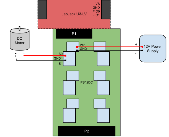
There is only 1 external power supply, and 1 item being controlled.
Figure A2. Multiple Items
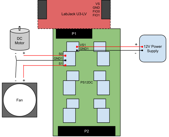
There is 1 external power supply, and 2 items being controlled.
Figure A3. Multiple Power Supplies
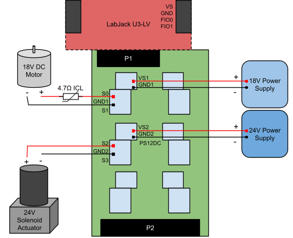
There are 2 power supplies, and 2 items being controlled. The high voltage DC motor requires a 4.7Ω inrush current limiter to help protect the PS12DC from the large inductive load inherent to a DC motor. See Appendix D for more information.
Figure A4. Multiple Items, Single Supply
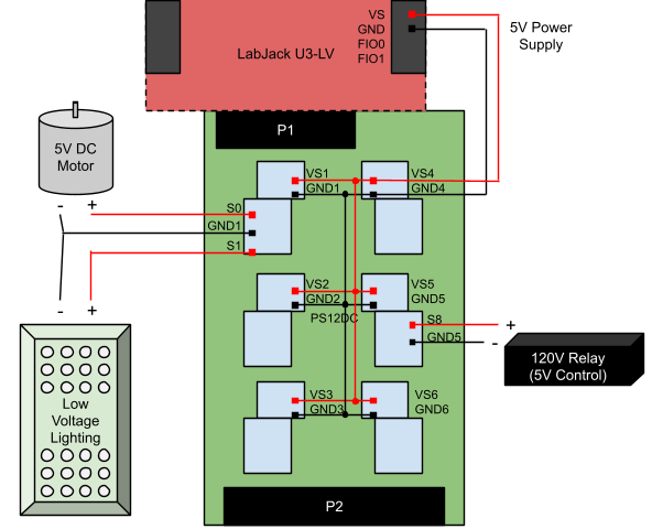
5V is distributed to all 6 power supply blocks. All 12 switches are fed 5V from the LabJack. This is a common configuration for simple testing, since the LEDs will illuminate when the LabJack is powered on, and it does not require an external power supply.