-
5 to 28V supply voltage
-
750mA per channel
-
Thermal (self-resetting) fuse protected >1.5A per pair
-
Flyback protection >33V
-
Operating temp −40 °C to 85 °C
-
Maximum switching frequency: ~6kHz (see Switching Frequency section)
When at the upper limit of its operating voltage and current, the PS12DC can become hot to the touch; This is normal, but can be managed by supplying a fan or heat sink to the backside of the board. Reference the information below for further details on current limitations, and behavior at extreme temperatures.
Digital States
What a switch will do in each of the 3 LabJack I/O states.
-
Output-high: Switch ON, the S# screw terminal will be at VS#
-
Output-low: Switch OFF, the S# screw terminal will be at ~GND#
-
Input: Switch is weak ON, due to LabJack internal pull-up resistors. LED will light up without anything on the switch, but marginal load on the switch will drop the output voltage significantly, and turn off the LED. Because behavior is ambiguous, the input I/O state is not recommended.
LEDs
Each LED is powered by the voltage connected on VS#/GND# (the power supply provided by the user). If a power supply is connected to the switch block, e.g. VS1/GND1, and a positive voltage is applied to the digital inputs for that block, the LEDs will illuminate. An illuminated LED means that the switch is ON, and the voltage applied to the block is available at that switches' screw terminal.
Current Limit
The 750mA per channel rating is a base specification, but the board actually has a Per Switch and Per Pair rating. If only a single channel in a channel pair is in use, the per switch limit applies. If both channels in a channel pair are used, the per pair limit applies. Channel pairs are distinguished by the grouping of screw terminals. For instance, S0, and S1 constitute a pair, so you would connect the high current item(>750mA) to S0, and leave S1 un-connected.
Table D1. Current limits based on supply voltages
|
|
Current Limit |
|
|
Supply Voltage (V) |
Per Switch (A) |
Per Pair (A) |
|
|
|
|
|
5 |
0.5 |
1.0 |
|
9 |
0.7 |
1.4 |
|
12 |
1.0 |
1.5 |
|
18 |
1.1 |
1.5 |
|
24 |
1.5 |
1.5 |
|
28 |
1.5 |
1.5 |
There is a voltage drop across the switch associated with load current when using the PS12DC. It is rated at 750mA per channel, but it is recommended that at 5V, a load current of 500mA not be exceeded, since above this current the drop will be significant. Reference the graph below for details.
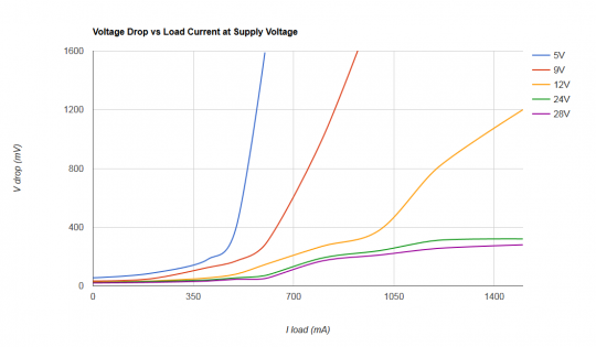
From a usage standpoint, the only items in the Typical Applications section that may draw more than 450mA are those involving motors. Before purchase, it is advised that you reference datasheets for the items to be controlled. If the current draw exceeds 1.5A on a power switching pair, this board will cut off power to avoid damage to itself.
Note: If you need a product that can handle more than 1.5A, the RB12 is a good option, although you will need to purchase the actual relay modules separately.
Switching Frequency
The switching speed of the transistors on the PS12DC are fast(4-18µS), but there is a substantial amount of capacitance on the S# terminals, so the falling edge will be delayed by large load resistances. Thus, to achieve fast switching frequency, it is necessary to discharge the capacitance through a small resistor. Simply add a 100Ω resistor between the switch output and the GND terminal (in parallel with whatever you have connected to the switch output). With a 100Ω resistor installed, the switching frequency is on the order of 2.5kHz.
Table D2. Switching frequencies based on load resistance
|
Load Resistance (Ω) |
Fmax (Hz) |
|
|
|
|
47 |
6,000 |
|
100 |
2,500 |
|
1000 |
400 |
|
10000 |
120 |
Note that it is possible to install smaller resistor values(<47Ω) to further increase switching frequency, but the resistor should have a high enough power rating to handle the heat.
Temperature Related Characteristics
The PS12DC becomes warm under continuous usage; This is normal, but if the average board temperature becomes too hot, the fuses will trigger somewhat before their rated 1.5A maximum, and the board could end up cycling on/off intermittently depending on how fast it cools between cycles.
This temperature dependency is directly related to the thermal derating curve on the resettable fuse. The fuse trip current drops about 50% at the highest end of its operating temperature. See the graph below for further details.
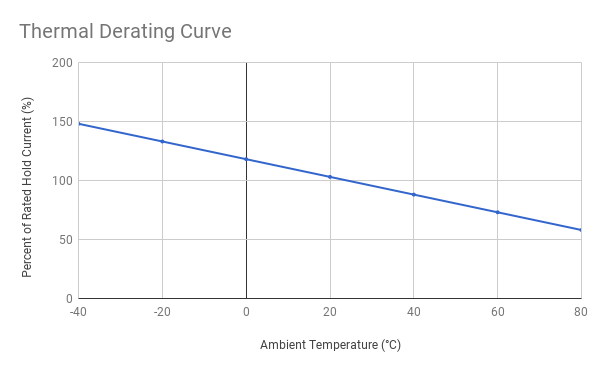
Adding heat sinks to the transistors can increase the per switch current limit, but exact figures depend on factors such as heat sink material, passive vs active cooling, and establishing good thermal contact with the transistor case. Bear in mind that the current limit of the resettable fuse is still temperature dependent, so any gains due to heat sinks would still be limited by the fuse holding current, which is 1.5A at 25 °C.
Large DC motors
If using a larger DC motor (above 12V DC, or bigger than 1" diameter as a general rule), we recommend installing supplementary snubber diodes, and inrush current limiters, as large flyback and inrush currents can overwhelm the protection circuitry on the PS12DC, resulting in damage.
Voltage equation is V = E - IaRa
where
V = terminal voltage
E = Back emf
Ia = Armature current
Ra = Armature Resistance
In the beginning E = 0 and V = IaRa
where Ra is always very low, about = 0.01 ohm
So, if you calculate for Ia = V/Ra, you will get large current.
Using the equation above, if you have a 24V DC motor, and the armature resistance is 0.01ohm, the current spike would be very large. In order to protect the PS12DC, a 5Ω to 15Ω inrush current limiter installed in series with the motor wiring would be sufficient to protect the PS12DC. This B57153S479M 4.7Ω inrush current limiter is a good option for 12V to 24V DC motors in the 750mA to 1.5A range. We also tested this B57153S100M 10Ω inrush current limiter up to 28V DC, and it worked well.
Select an inrush current limiter based on the current required during normal operation. For example, if I'm using a 24V DC motor, and normally the motor will draw about 1A of current, I would select a limiter of 4.7Ω at 25C, and around 2A steady state max. Inrush current limiters basically have some resistance when their temperature is equal to ambient, and then as the part heats up, the resistance drops substantially. So if the motor draws 1A of current during normal operation, the resistance of the current limiter will drop from 4.7Ω to a lower resistance(~0.5Ω) during normal operation.
If you don't mind sinking some extra power, and a voltage drop, you could simply install a very high wattage resistor in series. A 5Ω 20Watt resistor would protect as well as an inrush current limiter, but at 24V, and 750mA, there would be a voltage drop of 3.75V. The resistor would get warm (super hot) because it'd be sinking 18W of power during normal operation. Here is an example of a 5Ω 20W resistor.