The LJTick-LVDigitalIO (LJT-LVDIO) A bidirectional logic shifting board for converting 3.3V logic down to 2.5V or 1.8V. There is also a VOUT terminal which can source power at the selected voltage. Useful for users who have external boards that run on lower logic thresholds, or simply want a 3.3V, 2.5V, or 1.8V supply.
-
Supports bi-directional communication
-
Up to 800kHz
-
3.3V, 2.5V, or 1.8V
-
VOUT terminal can source up to 200mA
Note: Advanced users may convert the 1.8V option to 5V by installing a jumper on R5, and removing or destroying the voltage regulator marked U3. Instructions for doing this can be found on the modifying the LJTick-LVDigitalIO page.
Subsections
Common Applications
-
Communicating with SPI, I2C, UART, 1-Wire, and other Digital IO sensors that require a supply voltage that is the same voltage as the logic level.
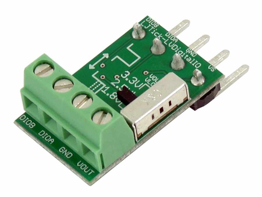
Screw Terminal Descriptions
Vout: This voltage can be selected to be either 3.3V, 2.5V, or 1.8V with the slide switch.
GND: Same as LabJack ground (GND).
DIOA/DIOB: These logic input and output lines can be configured to communicate with 3.3V, 2.5V, or 1.8V circuitry.
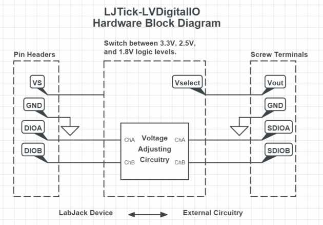
LJTick-LVDigitalIO Hardware Block Diagram
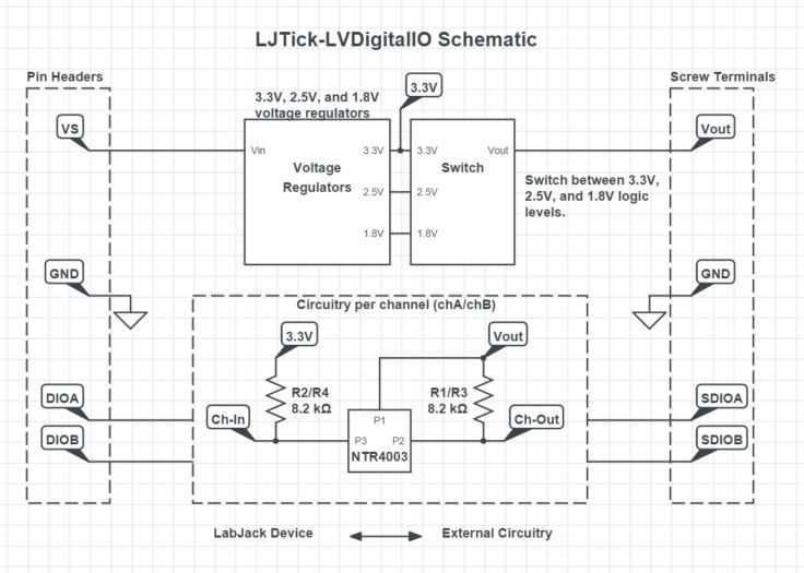
LJTick-LVDigitalIO Schematic
Specifications
|
Parameter |
Conditions |
Min |
Typical |
Max |
Units |
|
Supply Voltage |
|
3.6 |
|
5.25 |
V |
|
Supply Current |
No Load |
|
0.2 |
|
mA |
|
Operating Temperature |
|
-40 |
|
80 |
°C |
|
Output Drive Current |
|
|
100 |
|
mA |
|
|
|
|
|
|
|
|
1.8V Logic Voltage |
|
|
|
|
|
|
Vout Output Voltage |
|
|
1.8 |
|
V |
|
Vout Current |
|
|
300 |
|
mA |
|
Rise time |
|
|
180 |
|
ns |
|
Fall time |
|
|
580 |
|
ns |
|
Max Recommended Frequency |
No load, 50% duty cycle |
|
1 |
|
MHz |
|
Logic High |
|
|
1.78 |
|
V |
|
|
|
|
|
|
|
|
2.5V Logic Voltage |
|
|
|
|
|
|
Vout Output Voltage |
|
|
2.5 |
|
V |
|
Vout Current |
|
|
300 |
|
mA |
|
Rise time |
|
|
560 |
|
na |
|
Fall time |
|
|
640 |
|
na |
|
Max Recommended Frequency |
No load, 50% duty cycle |
|
1 |
|
MHz |
|
Logic High |
|
|
2.46 |
|
V |
|
|
|
|
|
|
|
|
3.3V Logic Voltage |
|
|
|
|
|
|
Vout Output Voltage |
|
|
3.3 |
|
V |
|
Vout Current |
|
|
300 |
|
mA |
|
Rise time |
|
|
2 |
|
ns |
|
Fall time |
|
|
800 |
|
ns |
|
Max Recommended Frequency (1) |
No load, 50% duty cycle |
|
1 |
|
MHz |
|
Logic High |
|
|
3.26 |
|
V |
|
Logic High (Vmax) at max frequency |
1MHz, no load, 50% duty cycle |
|
3.1 |
|
V |
(1) Frequencies higher than 350kHz will not produce the full logic high voltage.
For more specifications about the MOSFETs and voltage regulators used in the LJTick-LVDigitalIO look at the following datasheets:
-
ON Semiconductor (Logic Level Shifters) NTR4003N datasheet.
-
Diodes Incorporated (3.3V Regulator) AP2127K-3.3TRG1 datasheet
-
Richtek (2.5V Regulator) RT9193 datasheet
-
Diodes Incorporated (1.8V Regulator) AP2127K-1.8TRG1 datasheet
CAD
Files
ON-Semiconductor-NTR4003N-Datasheet.PDF