For the nominal maximum analog input voltage ranges of our devices, please visit their Appendix A sections in the appropriate Users Guide or datasheet.
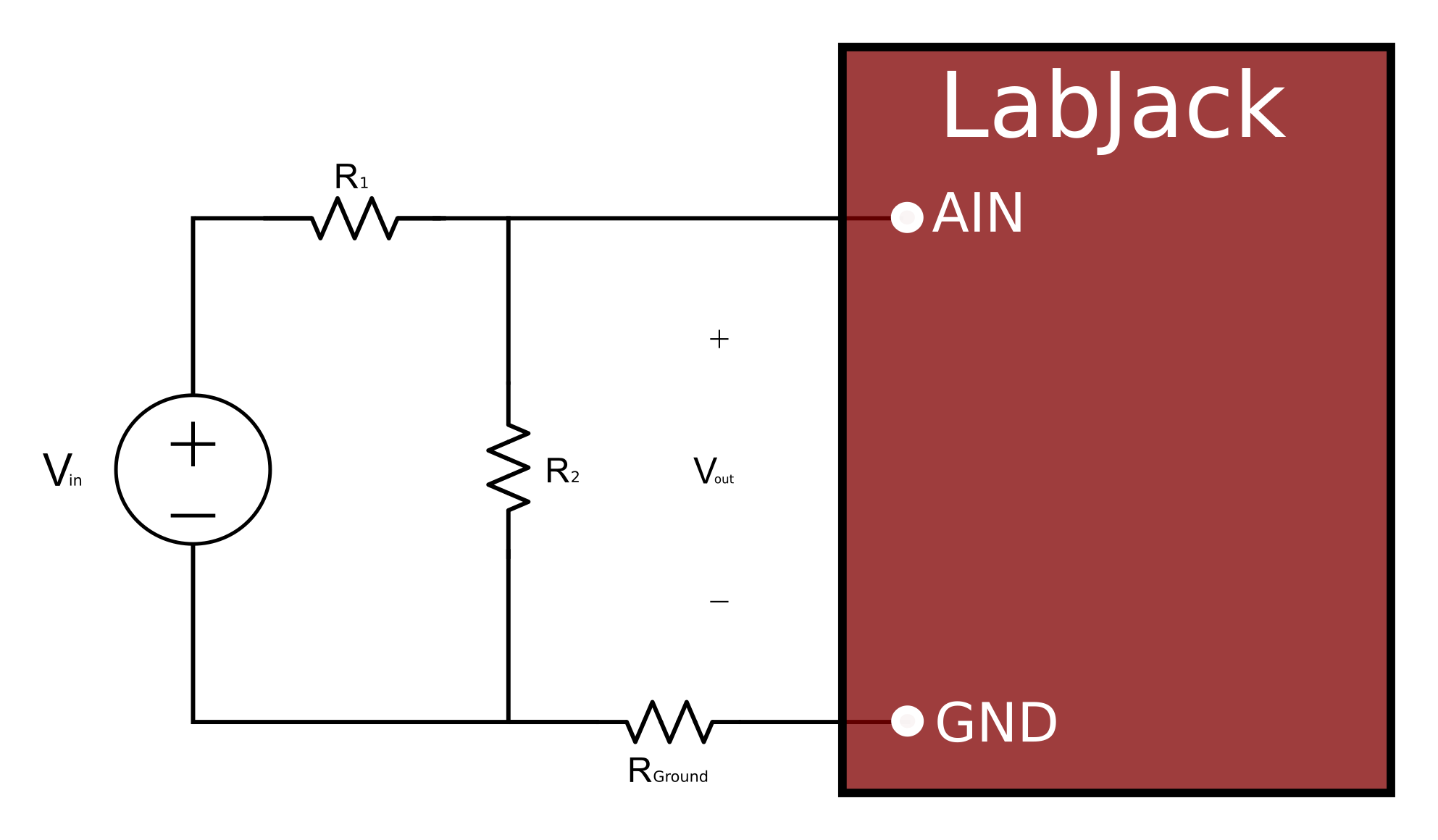
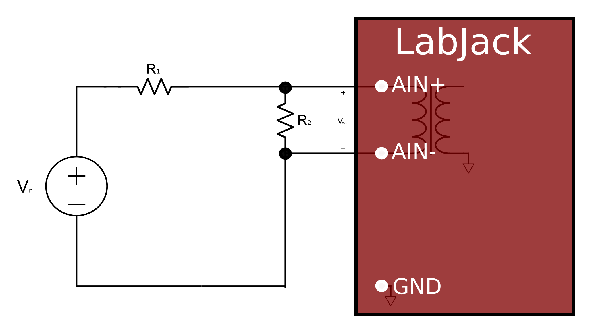
The simplest way to handle higher voltages is with a resistive voltage divider. The following figures show typical resistive voltage divider circuits.


The attenuation of this circuit is determined by the equation:
Vout = Vin * ( R2 / (R1+R2))
This divider is easily implemented by putting a resistor (R1) in series with the signal wire, and placing a second resistor (R2) from the AIN terminal to the most appropriate ground. To maintain analog input performance across all gains and resolutions, R1 should not exceed the values specified in Appendix A of your device device datasheet. R1 will often be fixed at the max recommended value and R2 can be adjusted for the desired attenuation.
Buffered Voltage Divider
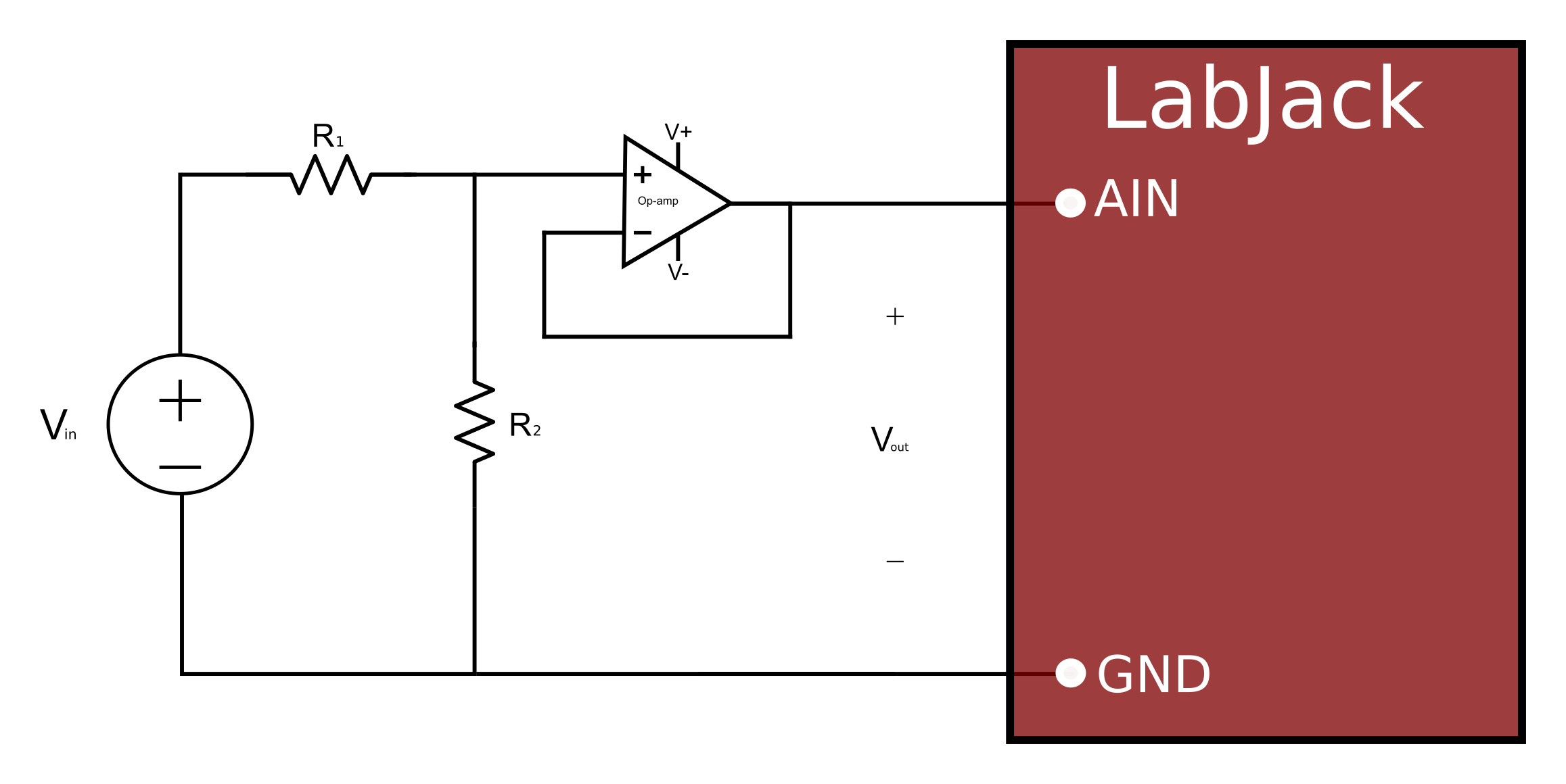
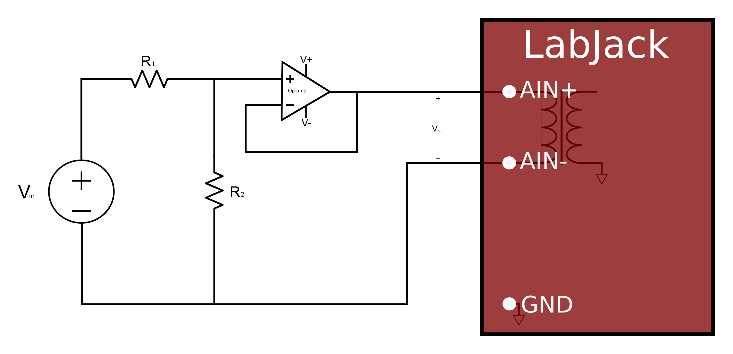
The divide by 2 configuration where R1 = R2 = 1 kΩ, presents a 2 kΩ load to the source, meaning that a ±10 volt signal will have to be able to source/sink up to ±5 mA. Some signal sources might require a load with higher resistance, in which case a buffer should be used. The following figures show a resistive voltage divider followed by an op-amp configured as non-inverting unity-gain (i.e. a buffer).


The op-amp is chosen to have low input bias currents so that large resistors can be used in the voltage divider. The LT1490A from Linear Technologies (linear.com) is a good choice for dual-supply applications. The LT1490A only draws 40 µA of supply current, thus many of these amps can be powered from the Vm+/Vm- supply on the U6 or T7, and can pass signals in the ±10 volt range. Since the input bias current is only -1 nA, large divider resistors such as R1 = R2 = 470 kΩ will only cause an offset of about -470 µV, and yet present a load to the source of about 1 megaohm.
For 0-5 volt applications, where the amp will be powered from Vs and GND, the LT1490A is not the best choice. When the amplifier input voltage is within 800 mV of the positive supply, the bias current jumps from -1 nA to +25 nA, which with R1 = 470 kΩ will cause the offset to change from -470 µV to +12 mV. A better choice in this case would be the OPA344 from Texas Instruments (ti.com). The OPA344 has a very small bias current that changes little across the entire voltage range. Note that when powering the amp from Vs and GND, the input and output to the op-amp is limited to that range, so if Vs is 4.8 volts your signal range will be 0-4.8 volts.
Another option is the LJTick-Divider which plugs into compatible LabJack device screw-terminals. It is similar to the buffered divider shown in Figure 2.
The information above also applies to resistance measurement. See our Measuring Resitance app note.
