Warning: In order to work with this device, one should be familiar with general electrical safety. The voltage used is dangerous to personal safety. Mistakes can lead to property damage or bodily harm. This project is only for individuals who are experienced with wall/mains wiring. It is the responsibility of the user to build the device to operate safely.
Summary
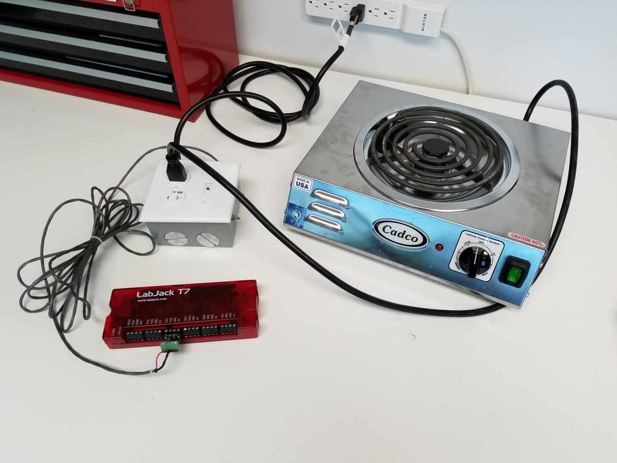
This box allows the user to control high voltage devices (up to 280 VAC, 40 A, depending on wire size and cooling ability) such as hot plates, heaters, lamps, and electric motors. This device was used for a pressure canner, where it controlled a hotplate using pulse-width modulation (PWM) to precisely set the heat output of the hot plate based upon the pressure of the vessel.
The receptacle shown here is rated for 20 A, but the cord that plugs into the wall is rated for 15 A, so 15 A is the maximum current that can be sourced by this device. For this project, it is recommended to use the Kyotto KD20C40AX 40 A, 280 VAC Solid-State Relay. This does not fully utilize the capabilities of the relay, but works for most applications, and minimizes cost. There are many options for solid state relays, the recommended relay should work for most applications. Because the recommended relay will be operating well below its maximum ratings, the heat output is manageable, and is easily dispersed into the surroundings. At 13 A load, the relay reached only 32°C (90°F), which is well within the operating range of the relay. Many solid-state relays, including the recommended relay, are optically isolated from the load side of the relay, which mitigates the possibility of damage to the LabJack.
Most 120 V devices under 15 A can be turned on or off with this relay box. Specific power control can be achieved through PWM control, but may not work for your application. Loads such as motors require the AC wave frequency to be modulated to change motor speed, rather than just supplying power for a small amount of time. While controlling the speed of an AC motor with this device is not possible, the motor can still be turned on and off with this relay box. Simple resistive loads, such as hot plates or lamps, can be controlled via PWM, since there isn't precise timing involved. See the Controlling Relays Application Note for more information.
Our selected solid-state relay only makes connection at zero crossings, where the AC voltage crosses 0 V. Due to the zero-crossing switching, this PWM signal is not perfectly scalable; it can only be adjusted in integer steps. By slowing the frequency of the PWM signal to 1 Hz, 60 steps of resolution between zero and full power is possible. A detailed understanding of zero-crossing circuits is helpful when implementing control by PWM.
To build the Solid-State Relay Box, the following materials must be purchased:
|
Part |
Description |
Quantity |
Price (USD) |
Part Number |
Link |
|
Solid State Relay |
Zero-Crossing, at least 15A |
1 |
19.95 |
KD20C40AX |
|
|
Tool Replacement Cord |
15A Minimum |
1 |
13.47 |
165018 |
|
|
Enclosure |
2-Gang Weatherproof Box with Five 3/4 in. Outlets |
1 |
15.23 |
WDB575G |
|
|
Outlet, Water Resistant |
15A, Water/Tamper Resistant Outlet |
1 |
3.79 |
R62-W5320-T0W |
|
|
2-Gang Cover Plate |
1 Toggle, 1 Duplex Outlet |
1 |
1.39 |
R52-0PJ18-00W |
|
|
Strain Relief |
1 in. Non-Metallic (NM) Twin-Screw Clamp Connector |
2 |
1.61 |
90513 |
|
|
Machine Screws, #8-32 x 1/2" |
For Solid State Relay Mounting |
1 pkg |
1.18 |
814201 |
|
|
Nylon Lock Nuts, #8-32 |
For Solid State Relay Mounting |
1 pkg |
1.18 |
802221 |
|
|
Washers, #8-32 |
For Solid State Relay Mounting |
1 pkg |
1.18 |
800321 |
|
|
Crimp Connector Assortment |
20AWG rings and 16AWG forks needed |
1 pkg |
9.97 |
TK-806 |
|
|
Control Wire |
10ft Stranded wire, 18AWG, cut to length |
10ft |
2.70 |
57573199 |
|
|
LED, Green |
Optional, for indicating when relay is on/off |
1 |
0.15 |
LG3330 |
|
|
Resistor, 220 Ohm |
Optional, for LED |
1 |
0.10 |
CF1/4W221JRC |
|
|
Thermal Paste |
For Solid State Relay cooling |
1 |
3.49 |
NTE303 |
|
|
|
|
Total: |
$72.24 |
|
|
The Build
1. Prepare the Enclosure for SSR Mounting
Take the enclosure and mark holes for the solid-state relay mounting screws. For our box and relay, these holes were 1-3/8" from the bottom and 1" from the center. Check that your solid-state relay fits before drilling the holes. The holes should fit a #8 machine screw, so use a 5/32" diameter drill bit.

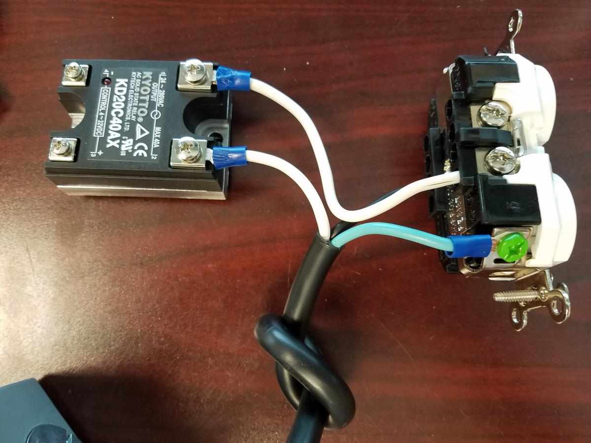
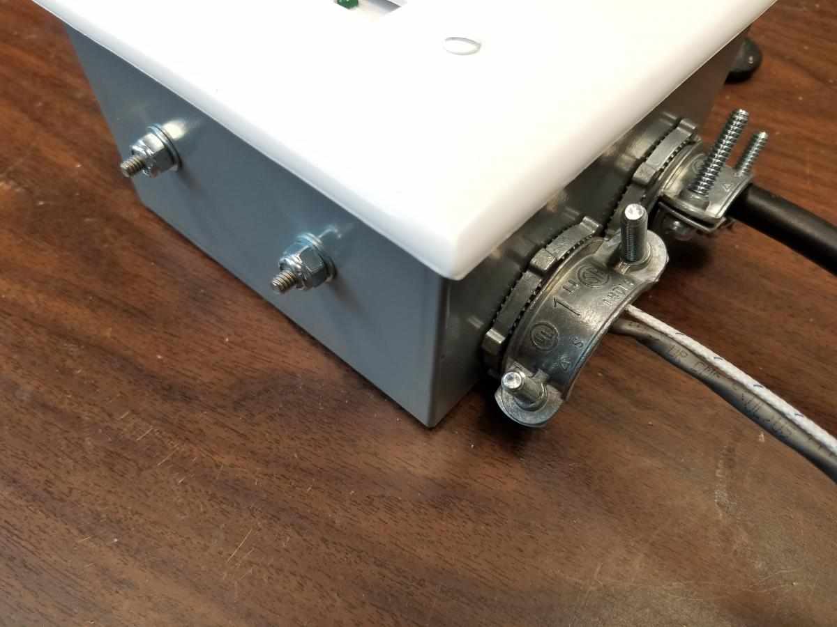
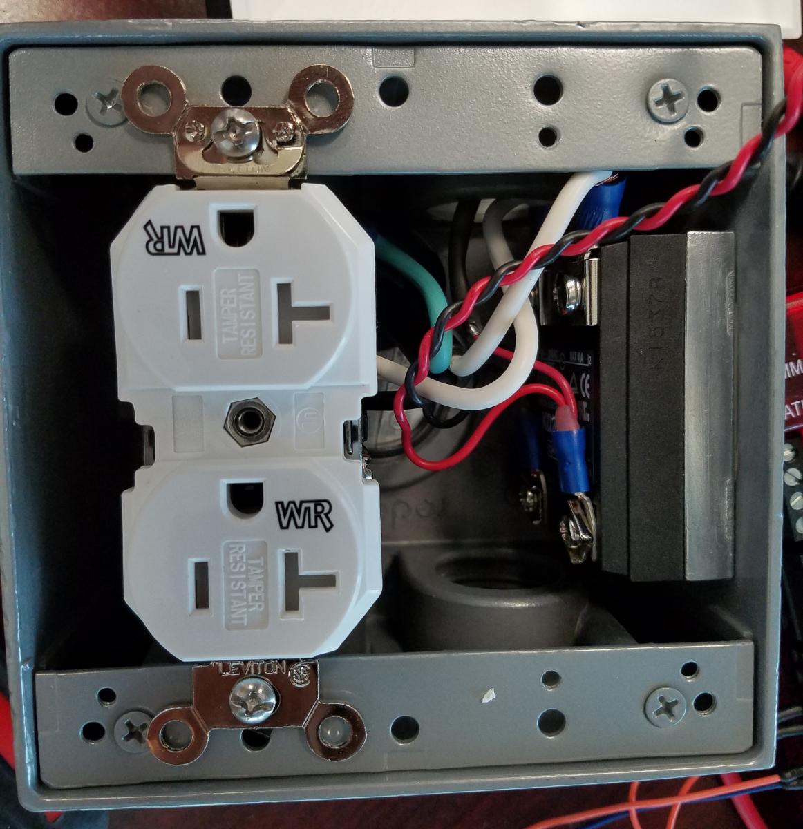
2. Wire the Outlet and SSR (AC Lines)
Install the wire clamps into the enclosure. Thread the cord into the box through a hole on the opposite side from the holes that were just drilled. You may need to bring the insulation back further to allow for the 3 conductors to reach the outlet and relay. A knot can be tied in the cable to prevent wire strain, but this step is optional. Connect the black wire to the black side of the outlet, the green to the green screw, and the white to a terminal on the relay (Terminal 2 on the recommended SSR) The output side of the SSR (1 on the recommended SSR) must be connected to the white side of the outlet. Spade-type crimp connectors may be needed for connections to the relay and/or outlet.
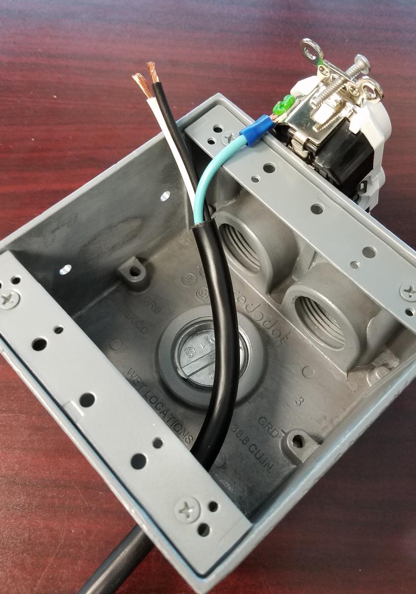
The black wire, not shown, should be connected to the black side of the outlet.
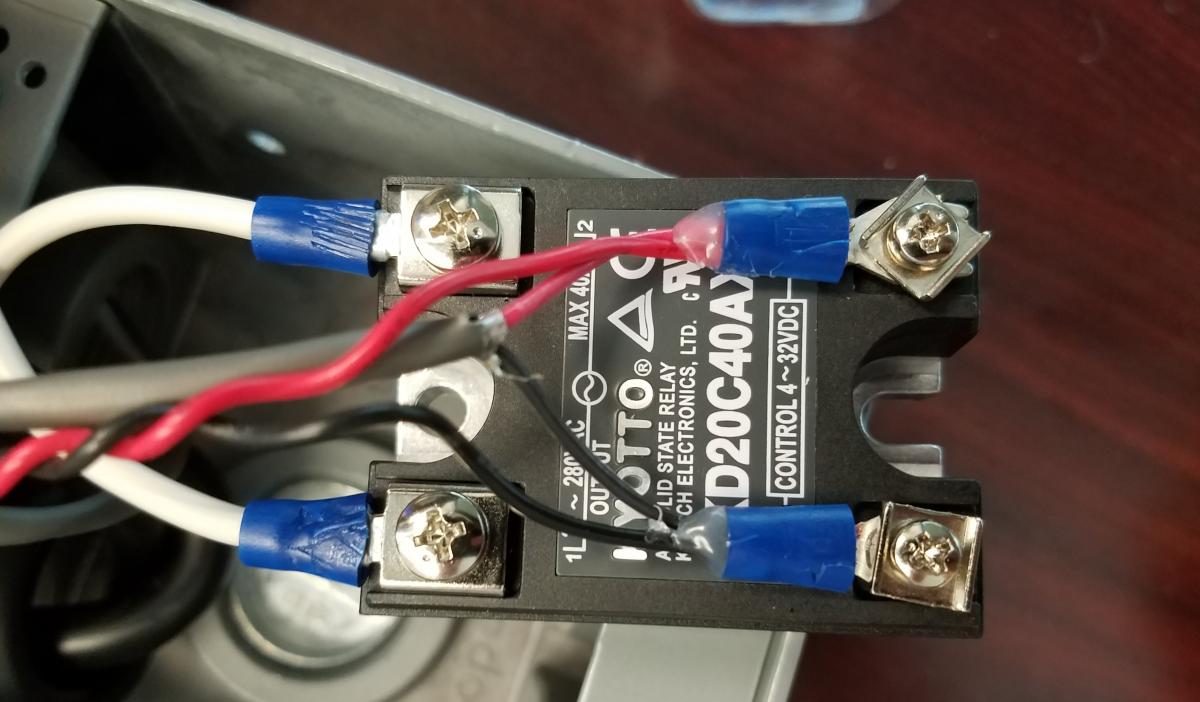
3. Wire the SSR Control Lines
Strip and connect the control wires to the control side of the SSR (3 and 4 for the recommended SSR) The LED (optional) can also be connected here.
4. Secure the SSR to the Enclosure
Apply thermal paste to the back plate of the SSR, and to the side of the enclosure. Press the solid-state relay to the side of the enclosure and move it into position. Insert the screws into the slots of the SSR and thread on a washer and nut to the tail of the bolt. Due to the tight space, a right angle screwdriver may be necessary to tighten the machine screws.
5. Add a Thermocouple For Temperature Monitoring (Optional)
A thermocouple can be attached to the heat sink portion of the SSR to monitor relay temperature. Heat will be sunk away from the SSR to the enclosure, via the thermal paste, where the heat can radiate to the surroundings.
6. Install the Outlet Using the Included Screws.
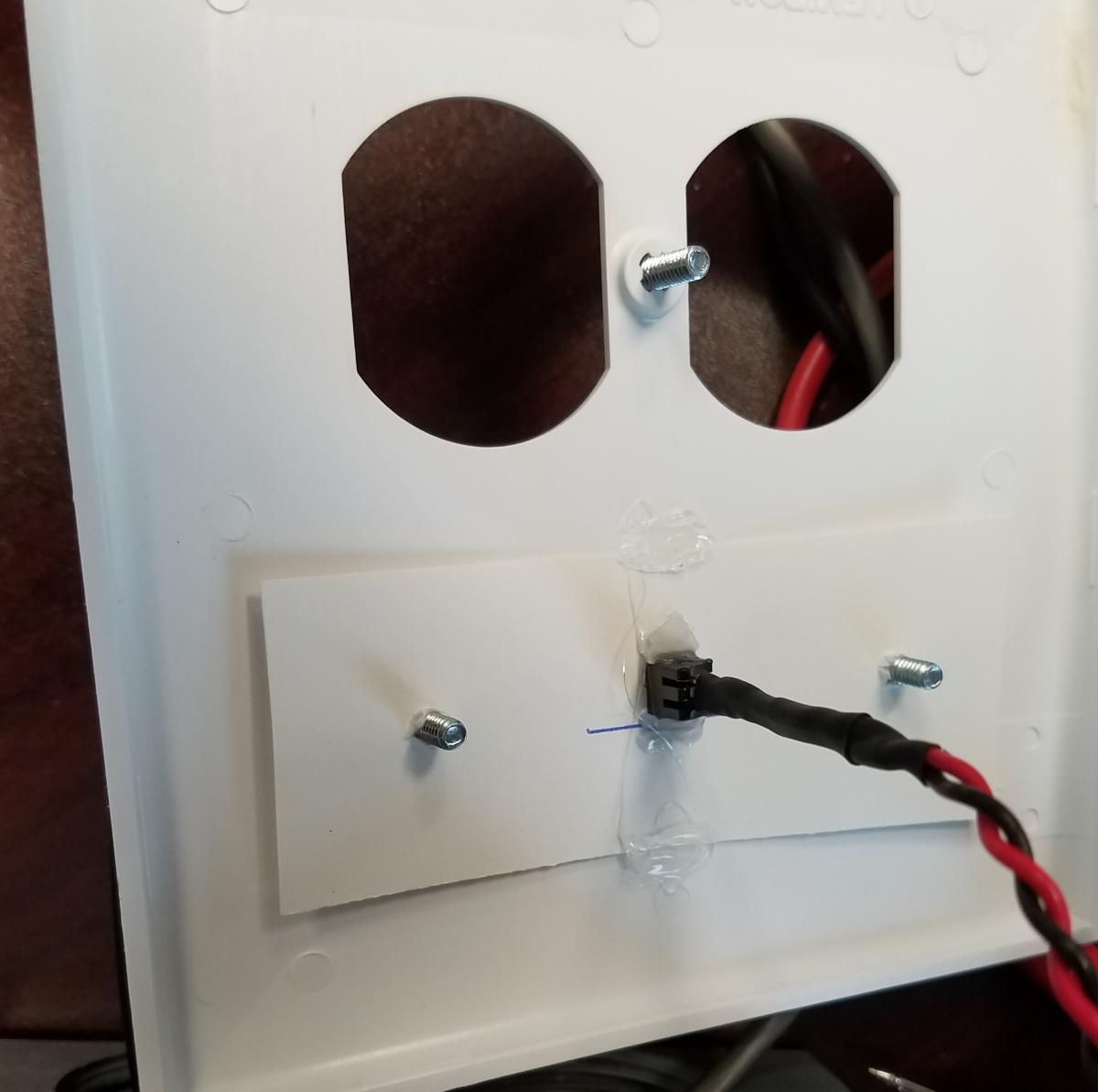
7. Mount the Face
Epoxy and white cardboard were used to mount the LED onto the faceplate, but other methods can be used.
8. Install the faceplate onto the enclosure with the provided screw. Tighten cable clamps if needed.
9. Control Line Wiring
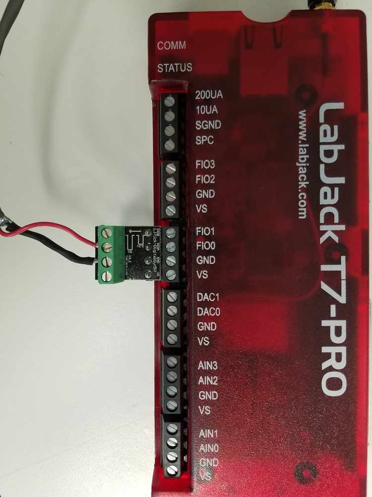
Connect the control wires to the LabJack. Depending on the relay, device, and application, there are multiple configurations that can be used to control the relay. For the recommended relay, there are two possible configurations: using a DAC to control the relay, or using an LJTick-DigtalOut5V, which shifts the FIO lines to 5V. The recommended relay is activated at 4V, per the datasheet, so the 3.3V level of the I/O lines will not work to control this relay. The method using the DAC allows on/off control, but cannot use the PWM functionality of the digital I/O lines. To use PWM control, the relay must be connected to the FIO lines through an LJTick-DigitalOut5V.
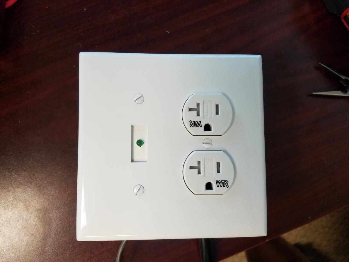
10. Control the Relay Box Using Software
Lastly, open the device in Kipling (or LJControlPanel for UD devices) and toggle the I/O line from Output-High to Output-Low. Plug the cord into the wall, and connect a lamp, hotplate, heater, or any other load within the current rating of the device. Continue toggling the I/O line to test the relay box and control the output device.
When controlling high-power devices such as heaters and motors, fail-safe design is important. It is the developer's responsibility to implement fail-safe design to prevent property damage or bodily harm.