This app note explains the operation and use of the 1-Wire bus in conjunction with LabJack products.
1-wire "overdrive" timings are not supported, only "standard" timings are supported.
1-Wire is considered an advanced topic. A good knowledge of the protocol is recommended. Troubleshooting may require a logic analyzer or oscilloscope.
Compatibility
-
T4: All recent firmware versions.
-
T7/T7-Pro: All recent firmware versions.
-
T8: Firmware v1.00 or later.
-
UE9: Control Firmware v2.20 or later.
-
U6: Firmware v1.17 or later.
-
U3: Firmware v1.31 or later.
-
U12: Not supported.
Overview of 1-Wire
The basis of 1-Wire technology is a serial protocol using a single data line plus ground reference for communication. A 1-Wire master initiates and controls the communication with one or more 1-Wire slave devices on the 1-Wire bus. Each 1-Wire slave device has a unique, 64-bit ID, which serves as its address on the 1-Wire bus. Slave devices typically operate over the voltage rage of 2.8 V to 5.25 V.
Some 1-Wire devices require a separate power supply, but many take their energy directly off of the data bus line—this is called parasitic supply. Because of this unique parasitic supply, 1-Wire is the only voltage-based digital system that works with two contacts, data and ground for half-duplex bidirectional communication.
Using a LabJack as the Master
Before attempting communication with a 1-Wire slave through a LabJack, insure the following conditions are met:
-
1-Wire compatibility with your LabJack
-
Only connect 1-Wire slave devices through EIO and CIO lines. The FIO lines have too much impedance to run 1-Wire properly*. Because EIO and CIO lines are only accessible through the DB15 connector, it may be helpful to purchase a CB15.
-
Parasitic or dedicated supply? Depending on power consumption the slave device may require a dedicated supply, or if it is a parasitic device, the correct pull-up and/or pull-down resistors need to be installed on the bus. Refer to the device datasheet for appropriate connections.
After the above conditions are met, it will be possible to initiate communication with 1-Wire slaves using a LabJack as the master.
UD-series devices: The low-level function for 1-Wire handles byte array command/response, and can be integrated into any program that has access to the device commutation protocol (USB, Ethernet, etc.) An example in LabVIEW is detailed below. There is no high level UD Library function for 1-wire at this time.
T-series devices: The LJM multiple value functions make it easy to operate 1-Wire. For examples:
-
LabVIEW: LabVIEW LJM examples
Search Algorithm
Using multiple devices on the 1-Wire bus requires that their 64-bit ROM codes be known. The codes can be found using a search algorithm. This search will identify the ROM codes of all devices on the bus, but will not reveal any information about the order they appear on the bus (physical location). The figure below represents 3 devices, and the branching that occurs during their discovery.
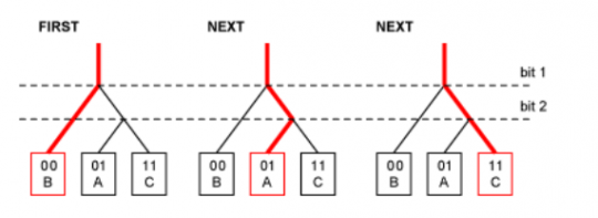
Each branch at a bit level denotes a difference in device ROM. These devices only have a 2-bit ROM.
Creating one of these search algorithms can be difficult, so when possible it is recommended to place a single device on the bus and use the master to identify its address. Based on design, if a 1-Wire slave device is alone on the bus, there will be no alternate branches for the master to search, so it will locate the device easily. After the device ROM is known, record it and identify the part with a marking or location.
More information on branching and search algorithms can be found in the following documents:
Overview on MaximIC: http://pdfserv.maxim-ic.com/en/an/AN1796.pdf
Searching for ROM addresses: http://pdfserv.maxim-ic.com/en/an/AN187.pdf
1-Wire Example
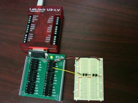
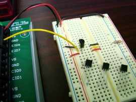
For this example a Maxim DS1822 digital thermometer is used to demonstrate the use of 1-Wire. The U3-LV running firmware v1.31 is configured as the master, and using a CB15; the 4 DS1822 temperature probes are connected to EIO6(DIO 14)**, VS, and GND. Below is a picture of the test setup.
Connections
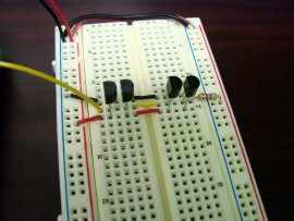
Since 5V (VS) is readily available on the CB15, and the DS1822 can be powered either directly or off of the bus (parasitic), it was connected directly to VS. Based on the datasheet, when connected in this manner it is appropriate to also include a pull-up resistor on the bus line. A 4.7kΩ pull-up resistor is seen on the right side.
DS1822 datasheet: https://datasheets.maximintegrated.com/en/ds/DS1822.pdf
Search ROM address
The next step is to discover the ROM codes that are factory programmed into the DS1822s. As mentioned above, it is easiest to connect a single device on the bus, then run the Read ROM command [33h]. The slave device will then return its 64-bit ROM. For convenience, a LabVIEW program capable of discovering ROM addresses on the 1-Wire bus can be downloaded at the bottom of the page.
Due to the way that 1-Wire devices may be used in practice, like in an expansive sensor network, it was decided that a search algorithm could greatly benefit our customers. The algorithm was developed in LabVIEW 6, and uses the Search ROM command [F0h] to investigate all of the branches necessary to reach each slave device. Once discovered, they are stored in memory and displayed on the control window. Although only tested in the above example, the algorithm executable can be downloaded below. The subVI is also available.
Reading The Temperature
After all of the ROM codes are known, simply use the Match ROM command [55h] followed by a 64-bit ROM code sequence to address a specific slave device on the bus. Before any communication can commence on the 1-Wire bus, the master will have to initiate this ROM command.
In order to capture the temperature data, one must carry out two additional command sequences; each one follows the Match ROM Command [55h].
-
The first is to make the temperature probe convert a temperature reading into a binary number. The Function Command for this is [44h], and must be issued in the first Tx data byte. See the low-level function reference for Tx Byte 0 location. Also set Num Tx to 1, for number of bytes to transfer.
-
The second sequence is required to read the binary temperature reading from the device memory. The associated Function Command is [BEh], and is also issued in the first Tx data byte. Again set Num Tx to 1, but this time it is also necessary to instruct the master to receive data. Set Num Rx to at least 2, because the first 2 bytes contain the binary temperature reading on the DS1822. Additional data can also be read from the device, see the datasheet for details.
For a complete communication description, reference DS1822 Operation Example 1 pg.18 in the datasheet. A simple LabVIEW program designed for reading the DS1822 can be downloaded below. Note that it will be necessary to know the ROM address of the slave probe before using the program.
Useful Code
These downloads were developed during testing, and were referenced in this app note. Please review the app note before use. All executables will require the LabVIEW 6.0 run time engine, which can be downloaded here (10.4 MB, save to desktop, right-click and do "extract here", run lvrteinstall.exe). SubVIs use some of the LabVIEW LJUD archive, so this will need to be downloaded and the appropriate subVIs referenced.
1Wire.vi
1Wire.exe
1Wire_Search.vi
1 Wire Search.exe
Read_DS1822.vi
Read DS1822.exe
1Wire_LJM.vi
1-Wire LJM Example .vi files
We also have a python examples for UD-series and T-series devices.
Notes
*The internal resistance on FIO lines could be reduced by changing the resistors, or using some form of dynamic pull up. We do not recommend modifying the LabJack; doing so may void your warranty.
**The DIO pin is important when using the downloadable subVIs and executables, insure correct number