Many of our devices are capable of communicating with sensors that only allow for serial communication. Most of our devices support SPI, I2C, 1-Wire, and other Asynchronous Serial Protocols. Configuring our devices to send and receive data is fairly device independent and easy once you understand the protocol being used, however a few things must be kept in mind before purchasing sensors that use a serial protocol for transferring information.
-
These serial protocols are not an alternative to the USB/TCP host connections on the LabJack. Rather, the host application will communicate with the LabJack via USB/TCP, and the LabJack can communicate with some other device/chip using a serial protocol.
-
Our devices supply 5V on their VS line, but have standard 3.3V logic levels. Watch out for chips with inputs that have a minimum logic high voltage of 0.7 * Vsupply, as that would be 3.5V with a 5V supply and not compatible with the 3.3V outputs on the LabJack. Note that with I2C the high voltage is generally controlled with a pull-up resistor anyway, so this is not a problem.
-
Our devices output 3.3V logic levels on their FIO/EIO/MIO/CIO lines, but are capable of receiving 5V as an input.
-
Some sensors don't follow standard I2C/SPI protocols.
-
SPI is generally easier than I2C. One big benefit to SPI is that you can do initial testing with a loopback wire from MOSI to MISO to confirm your software is working.
-
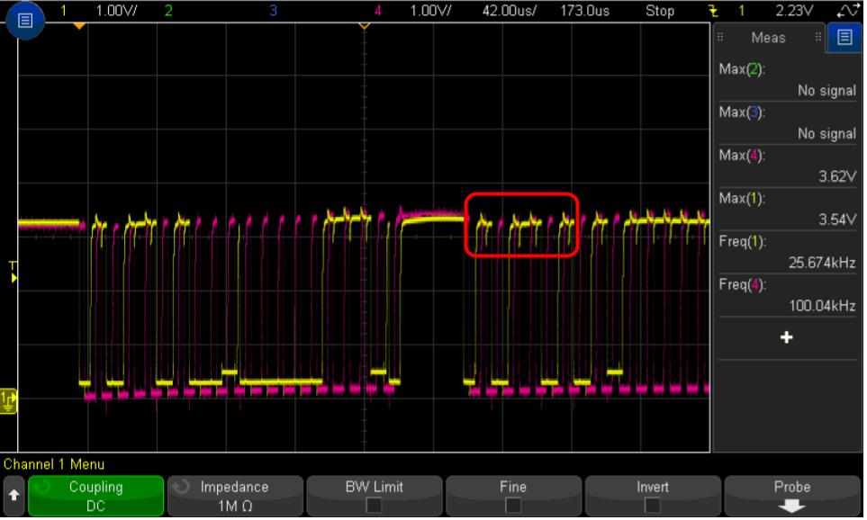
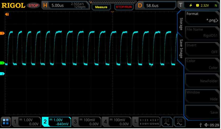
If you have trouble, an oscilloscope or logic analyzer might be required for troubleshooting.
-
The most complex part of these serial protocols is knowing what bytes/bits to send and how to interpret what you receive. You need to read the device's datasheet to determine that. In the event troubleshooting is required, you will also need to understand the timing diagrams in the device's datasheet.
Also see the applicable sections of the T-series Datasheet, U3 Datasheet, U6 Datasheet and UE9 Datasheet.
Further reading and Examples for I2C
Some posts and more resources about using LabJack devices with I2C sensors can be found below and on our website as well as in some external locations:
-
A website dedicated to the I2C Bus.
-
There are some I2C examples for LabVIEW, Matlab, and Lua for the UD devices as well as devices that support LJM on GitHub in the I2C-AppNotes repository. In particular, look at the LJM_I2C_Utils.m file for LJM compatible devices and the UD_I2C_Utils.m file for UD compatible devices.
-
For T-series LabJack devices: The T-series I2C Simulator is a quick visualization tool aimed to help users understand how the LJM I2C registers affect the resulting I/O data pattern that you would see on a logic analyzer.
-
The I2C AppNote and T-series I2C documentation describe some general properties about I2C and has some logic analyzer screen shots describing some of the I/O patterns.


