This app note explains the operation and use of the SPI protocol with our LabJack products and the SCA3000 3-axis accelerometer sensor.
Overview of SPI
The basis of SPI technology is a 4-wire serial communication protocol. One of the wires is chip select, driven low for the sensor that you wish to communicate with; another is clock, determines the speed at which data is transferred to and from the device; MISO (Master In Slave Out), the line that allows the slave device to give the master device information; and MOSI (Master Out Slave In), the line that allows the slave device to receive information from the master. Our LabJack devices are full duplex compatible so they transfer information out of the SPI register at the same time as information is put into the register (information that is read from the sensor).
Using a LabJack as the Master
Before attempting to connect a sensor to a LabJack device, make sure that the following conditions are met:
-
The device you are trying to use is 3.3V logic capable.
-
If you plan to use VS as the voltage source make sure that the sensor can be given 5V.
Once you are sure that the sensor you are trying to use is compatible with our device, you can continue. When you are trying to quickly use our LabJack devices and figure out a general flow of how tasks need to be done, the Python programing language and library that we have created is very convenient and easy to use and because there have not been any special requests, that is the language that will be used in this tutorial for the 3-axis accelerometer. In Python there is a function for each of our UD devices (U3, U6, and UE9) called "spi" with inputs: SPIBytes (the bytes you wish to transfer), AutoCS, DisableDirConfig, SPIMode, SPIClockFactor, CSPinNum, CLKPinNum, MISOPinNum, and MOSIPinNum. Every variable besides SPIBytes has a default setting, they are the following for the UE9:
-
AutoCS = True -
DisableDirConfig = False -
SPIMode = 'A' -
SPIClockFactor = 0 -
CSPinNum = 1 -
CLKPinNum = 0 -
MISOPinNum = 3 -
MOSIPinNum = 2
For more information on what each of these variables means please refer to our low level function reference guide. After properly configuring these settings you are now ready to send information to the sensor/connected device. You can follow the following Python code (for the UE9):
- python
# Import the UE9 class import ue9 # Open the first found UE9 d = ue9.UE9 # Sends two bytes 0,0. d.spi(SPIBytes=[0,0], AutoCS=True, DisableDirConfig = False, SPIMode = 'A', SPIClockFactor = 0, CSPinNum = 1, CLKPinNum = 0, MISOPinNum = 3, MOSIPinNum = 2)
Example (U3/U6/UE9 Compatible)
Overview and Connections
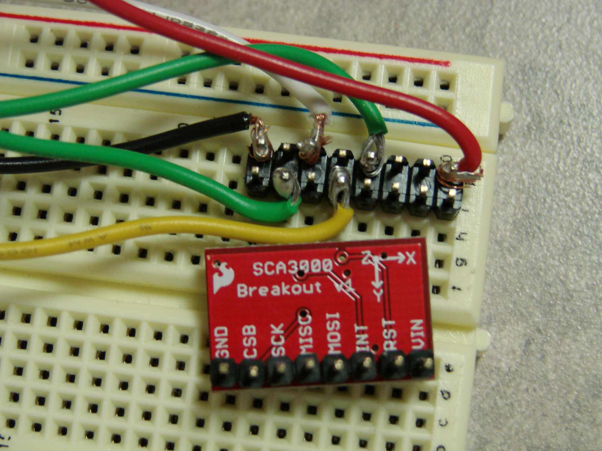
For this example a SCA3000 accelerometer is used with a UE9 device connected over USB. The firmware for the UE9 that is being used is Comm=1.4 and control=2.11 and the sensor is hooked up: Vs to VIN, GND to GND, CS to FIO1, SCK to FIO0, MISO to FIO3 and MOSIFIO2.
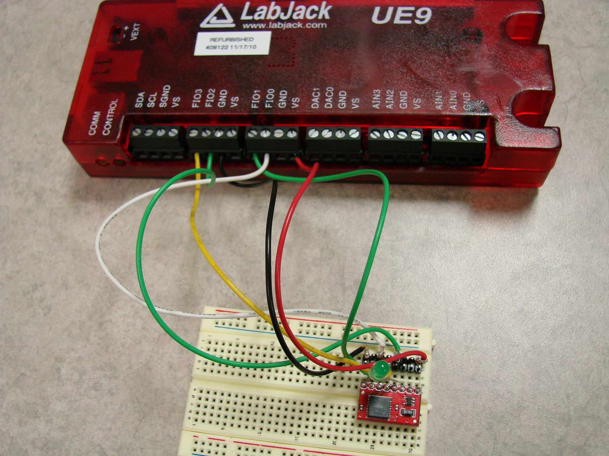
Note: there is an LED connected between the INT pin and GND because it will light up when the interrupt pin is enabled.
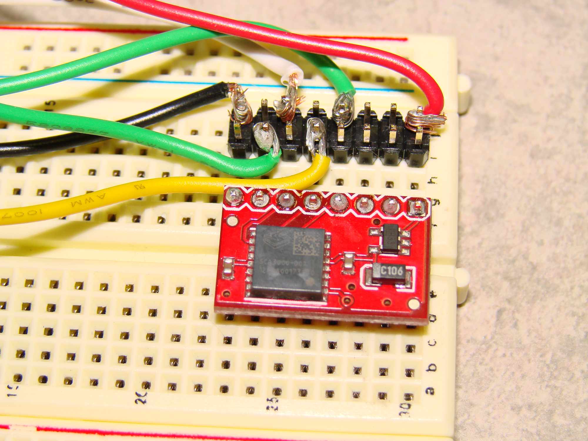
The sensor that we are using we purchased from SparkFun and was mounted to a break out board. Pin header's were mounted to the available holes so that it could be easily placed onto a breadboard. Look at the SparkFun page to find out how to wire the chip to expose the proper wires to your circuit if you plan on embedding this sensor onto a different PCB board. The datasheet that I referenced to set up this example can be found here. This datasheet, unlike many, was a very useful source of information and I did not need to do a lot of research to get information back from the sensor so I highly recommend looking at it. They have several useful examples in section 2 that I used.
A closer look at the sensor:
Basic information regarding sending SPI data to this sensor
At the start of section 4 in the datasheet you will find information regarding the SPI interface for this device. The most important information in this section is in 4.1.1 where they discuss what information needs to be sent to the device. The sentence, "The first 6 bits define the 6 bit address for the selected operation, which is defined by bit 7 ('0' = read '1' = write), which is followed by one zero bit." This means that all of the addresses they mentioned in the previous section are 6 bit addresses that all need to be shifted over 2 bits if you want to read from them (0x4h becomes 0x10h) or write to them (0x14h becomes 0x52h). This section also tells me that the sensor is full duplex meaning that it outputs information as information over the MISO line as information is received over the MOSI line. It also says that the data send to the master when receiving information is bogus information "don't care's" and that it ignores any information sent after a read command.
Reading spontaneous x, y, and z acceleration measurements
There are three basic steps that you need to follow in order to get information from the spontaneous data mode:
-
Make sure that you are in the correct mode (by default these sensors are in the spontaneous mode)
-
Read data from the proper addresses
-
Send out enough "don't care" bits so that a proper amount of information is received
Because the sensor is by default in the spontaneous data mode, I did not write information to the Mode register in my example, however if you wish to make sure that your sensor is, write a single 0 byte to the register (0x14h << 2) or 0x50h. After reading the datasheet I found out that the returned information was an 11bit number split into 2 bytes of data. To read specific acceleration measurements read from the following registers, each register holds one byte of data:
|
0x4h |
-LSBx |
|
0x5h |
-MSBx |
|
0x6h |
-LSBy |
|
0x7h |
-MSBy |
|
0x8h |
-LSBz |
|
0x9h |
-MSBz |
Pseudocode to read one of these registers:
d.spi([(0x4 << 2), 0x0]) #this reads the LSBx register
For a more in depth example of how to read multiple registers and how to convert the data to a more readable format please refer to the linked text file here. If wish to run this .py file you need to remove the _.txt from the end of the file name, also keep in mind that the function os.system("clear") only works for Mac/Linux, if you wish to run this example on a PC change "clear" to "CLS".
Ring Buffer Mode
There are three basic steps that you need to do in order to get information from the Ring Buffer Mode, there is an example of how to do this in section 2.5 of the datasheet:
-
Change the sensor's mode to "ring buffer mode"
-
Find out how much data is available in the buffer
-
Read the available information from the buffer
To explain a little bit more of what is going on, please look at section 3.1 of the sensor's datasheet where you will find a table with all of the available addresses that can be both read from, and written to. The address that we are looking to configure is the one named MODE" or 0x14h. Information about this address is on page 21, section 3.4. To put the sensor into this mode you simply need to enable the 7th bit, or write the value 0x80 to the 0x14h address. In the example I also enabled the 8 bit mode so I wrote 0xC0h to the 0x14h address.
d.spi([(0x14<<2), 0xC0])
The next step in order to use ring buffer mode you need to figure out how much information is available, you can do this by reading the BUF_COUNT register 0x15h.
d.spi([(0x15<<2),0x0])
The third step is to use this reported number from the previous line of psuedo code and send that many number of bytes -1 to the BUF_DATA register to read the collected acceleration measurements.
d.spi([(0xF<<2), 0x0...])
For an example of how to collect data please refer to the linked example here. If wish to run this .py file you need to remove the _.txt from the end of the file name, also keep in mind that the function os.system("clear") only works for Mac/Linux, if you wish to run this example on a PC change "clear" to "CLS".
The other important part to the ring buffer mode that needs to be understood is the interrupt function of this sensor. By default, the interrupt pin goes high when the buffer becomes half full, you can customize this if you wish in the INT_MASK register. If the buffer on your sensor gets half full the pin will go high and the only way to return the pin back low is to read the INT_STATUS address 0x16h:
d.spi([(0x16<<2), 0x0])
Further information
If you choose to use a different mode of this sensor, you can follow the examples from section 2 of the datasheet, they are all relatively straight forward to implement, simply configure the MODE register, and read data fro the proper addresses or read the interrupt pin to see if the specified event has occurred. If you choose to re-set the interrupt pin to get ready for the next event, simply read from the INT_STATUS address as mentioned above.