This application note explains the operation and usage of the I2C functionality for UD series LabJack devices. For I2C configuration support on T-series devices, see the T-Series Datasheet.
I2C is considered an advanced topic. A good knowledge of the protocol is recommended, and troubleshooting may require a logic analyzer or oscilloscope. We recommend users inexperienced with I2C purchase our LJTick-DAC and get I2C working with it before attempting configuration with a third-party sensor. LabJack does not typically provide support for specific I2C sensors beyond clarifying the necessary I2C configuration steps. Some general troubleshooting guidance can be found below.
Devices Discussed
-
UE9
-
U6
-
U3
Subsections
Options for using I2C on LabJack devices
In general, our LabJack devices have two primary ways of being configured. They can be controlled using our High Level LabJackUD Driver, recommended when using a Windows PC, or they can be controlled using low level functions. This application note will focus on our high level driver.
Overview of I2C communication using the UD Library
Before sending I2C commands using our devices it is important to understand the available functions that can be used in the UD Driver. The most useful functions are AddRequest and GoOne. Using these two functions you can configure, send, and receive I2C commands. In order to send I2C information using UD LabJack devices you need to follow three simple steps.
-
Connect the Sensor
-
Configure the I2C Data Bus
-
Figure out how data needs to be sent and send it using the proper read and write commands
Connect the Sensor
One of the most common causes of I2C issues is a minor sensor connection error. Always double check that your sensor is properly connected to a good, valid supply voltage and GND. Make sure that there are pull up resistors from the SCL and SDA lines to the supply voltage. Some common pull up resistor values are 1.8 kΩ, 4.7 kΩ and 10 kΩ. For our application note examples we typically use 4.7 kΩ resistors.
Configure the I2C Data Bus
There are five pieces of information that you need to configure before you can start communicating with your sensor.
-
Finding the preprogrammed address of the sensor
-
Deciding what pin on the LabJack will be connected to the SCL pin
-
Deciding what pin on the LabJack will be connected to the SDA pin
-
Defining the I2C options register (most complicated)
-
Adjust the clock speed of the I2C bus
1. The first step in configuration is to search the sensor's datasheet and find a 7 bit address that the sensor is preprogrammed to respond to. You then need to shift this address over one bit (5A (7 a bit address) becomes B4 (8bit address)). If the datasheet for your device gives you an 8 bit address you should be able to use this address with out shifting it. This is required because our High Level Driver needs to be able to change the smallest bit to indicate that you are either trying to read or write to the sensor.
2-3. The second and third steps is to decide what pins are going to be defined as SCL and SDA and then simply define them in your code.
4. The fourth and most complicated step is to configure the I2C Options. There are three settings that you can change here, you can enable clock stretching, tell the LabJack device to not stop transmitting when restarting, and you can tell the LabJack to Reset at Start.
-
Clock stretching is a fairly uncommon feature, but it allows the I2C slave to slow down the master when it needs to do more calculations or processes before data becomes available. A more detailed description of what this feature means can be found here.
-
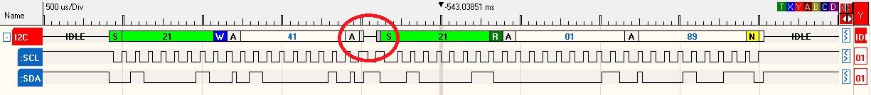
Enabling "No Stop when restarting" tells the LabJack not to send a stop condition when sending more than a single command at once. Most I2C devices require you to write some information to the sensor in order to tell the sensor what information you will be requesting later and if you do not want there to be a pause in communication this should be enabled. A good picture showing the difference in transmission that occurs from toggling this setting are below:
The circled area is the brief pause between a write command (left) and a read command (right). FYI address 42 was configured in these two pictures. Sensors will recognize 21 as the address with a write or read bit following the address.
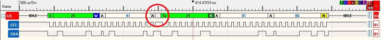
The circled area is where the pause used to exist between a write command (left) and a read command (right)
-
Enabling Reset at Start tells the LabJack to send 9 clock pulses before transmitting data to clear any half transmitted information that the sensor may think it has been sent. Times where you may want to enable this feature are when your LabJack lost power in the middle of transmission and your sensor didn't, when there may be a lot of noise along the SCL and SDA lines that could cause the devices connected in parallel to think they have received something but didn't, or other setups that require a robust I2C setup.
All three of these settings are packaged into a single byte that gets passed into the "AddRequest" function as a byte. These parameters get added together to get an integer from 0 to 255 that gets sent to the LabJack. If you wish to enable clock stretching, add 2^3 or 8, if you wish to enable "no stop when restarting" add 2^2 or 4, and if you wish to enable "Reset at start" add 2^1 or 2.
5. The last option that you can configure is the speed adjust parameter. This allows the communication frequency to be reduced. 0 is the maximum speed of about 150 kHz. 20 is a speed of about 70 kHz. 255 is the minimum speed of about 10 kHz.
Pseudocode for Configuration
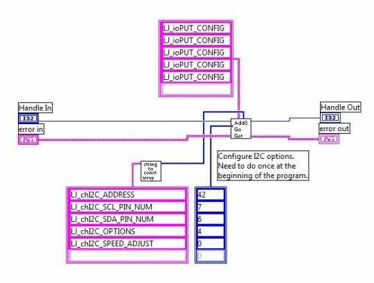
Now that you have all of the configurations figured out, you can now prepare the information to be sent using the AddRequest function, this can be easily shown through some pseudocode (an example for configuring our LJTick-DAC using I2C here). As an example, we will build the code that sent the above transmission over I2C.
//The following code configures I2C to try and communicate to the sensor/device responding to address 21
AddRequest(lngHandle, LJ_ioPUT_CONFIG, LJ_chI2C_ADDRESS_BYTE, 42, 0, 0);
//The following code configures I2C to use FIO7 as the SCL output pin
AddRequest(lngHandle, LJ_ioPUT_CONFIG, LJ_chI2C_SCL_PIN_NUM, 7,0,0);
//The following code configures I2C to use FIO6 as the SDA output pin
AddRequest(lngHandle, LJ_ioPUT_CONFIG, LJ_chI2C_SDA_PIN_NUM, 6,0,0);
//The following code configures I2C to enable the "no stop when restarting" I2C feature
AddRequest(lngHandle, LJ_ioPUT_CONFIG, LJ_chI2C_OPTIONS, 4,0,0);
//The following code configures the speed of transmission, sets SpeedAdjust to 0.
AddRequest(lngHandle, LJ_ioPUT_CONFIG, LJ_chI2C_SPEED_ADJUST, 0,0,0);
After all of these AddRequest functions have been called you need to execute the configuration requests:
//The following code executes the configuration requests
GoOne(lngHandle);
Because this tutorial was designed around the use of LabView, I will note a useful VI that we have created and are distributing that you can download and use here. It is called "AddS-Go-Get.vi" located in the following directory: "LabVIEW_LJUD\Utility VIs\AddS-Go-Get.vi" This VI takes in all of these settings, calls the AddRequest function for each of them, and then calls the GoOne function, we recommend that you use this VI when using LabVIEW on a Windows PC.
You can also download the Configure_I2C.vi a code snippet from a later VI that uses the AddS-Go-Get.vi and configures the LabJack to send I2C information.
Transmission
After you have properly configured the LabJack to communicate over I2C there are three more options that our High-Level driver exposes for you. You can use the commands LJ_chI2C_WRITE, LJ_chI2C_GET_ACKS, and LJ_chI2C_READ. These functions allow you to set up what information you want to send to the sensor (write), reports how many ACK bits were sent from the slave (get_acks), and reads back a given amount of information that is transmitted by the I2C device (read). Figuring out the information that you need to transmit to the sensor and how much information you will be looking to receive from the sensor are where problems start to arise. You can get bad results for many reasons including but not limited to trying to talk to an invalid address, using an invalid configuration, or sending the device a bad write array.
Pseudocode for Transmission
To finish off creating the transmission in the above pictures, we need to add a write command where we write 0x41 and then read 2 bytes of information.
//build write request
numWrite = 1;
array[0]=0x41;
AddRequestPtr(lngHandle, LJ_ioI2C_COMMUNICATION, LJ_chI2C_WRITE, numWrite, &array, 0);
//build read request
numRead = 2;
AddRequestPtr(lngHandle, LJ_ioI2C_COMMUNICATION, LJ_chI2C_READ, numRead, &array, 0);
//Execute the requests
GoOne(lngHandle);
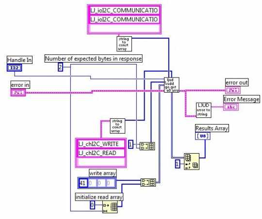
We recommend that you download this VI instead of trying to copy it, you can find it here. The "ljud eadd go get u8 array" vi that is used can be found in the same download as before, but in this directory "LabVIEW_LJUD\LabJackUD DLL Functions\LJUD_eAddGoGet (U8 Array).vi".
Another useful function that can help you debug some common I2C problems is the LJ_chI2C_GET_ACKS function. A useful VI that combines the read, write, and get ACKs functions can be found here. Pseudocode for doing this looks exactly like the transmission code except there is an extra eGet (or equivalently an AddRequest and GetResult) statement:
//tell the LabJack to count the ACK bits
eGet(lngHandle, LJ_ioI2C_COMMUNICATION, LJ_chI2C_GET_ACKS, &valACKs, 0);
For more examples of I2C implementation, you can look at the other AppNotes that we have created that communicate with I2C devices, look at example code in the LabVIEW download, look in the corresponding Python library for your device, or look at example code for our LJTick-DAC.
Further reading and Examples for I2C
Some posts and more resources about using LabJack devices with I2C sensors can be found on the forums section of our website as well as in some external locations:
-
A website dedicated to the I2C Bus.
-
There are some I2C examples for LabVIEW and Matlab. In particular, look at the UD_I2C_Utils.m.
-
There are some detailed descriptions of I2C on UD devices on DAQFactory's forum regarding the MCP23017 I2C chip on a forum topic titled I2C Problem (MCP23017)
-
The T-series I2C Simulator is a quick visualization tool aimed to help users understand how the T-series I2C registers affect the resulting I/O data pattern that you would see on a logic analyzer. The T-series I2C interface has very similar configurations to UD devices, so it can be useful for UD devices as well.
I2C Troubleshooting
See our I2C Resources App Note.