This AppNote explains the operation and use of the I2C functionality of our LabJack devices with special regards to the Melexis HMC6352 IR temperature sensor. All example VIs created in this example were originally created in LabVIEW 6.0.2 and use our LabVIEW library found here.
Integration Notes for T-Series Devices
An example application of this sensor working with a T-Series device can be found in the I2C Lua Script Examples section: IR Temperature Sensor MLX90614. This example allows seamless data collection from a MLX90614 IR Temperature sensor and a computer when using LJLogM. Also see the T-Series I2C documentation.
Example (U3/U6/UE9 Compatible)
If you have questions about I2C functionality with our LabJack devices please refer to the I2C AppNote, the low-level function page or the high-level driver pseudocode for I2C. This pp note will deal with what information to transmit to the Melexis IR temperature sensor instead of focusing on how to send it.
Connecting the sensor
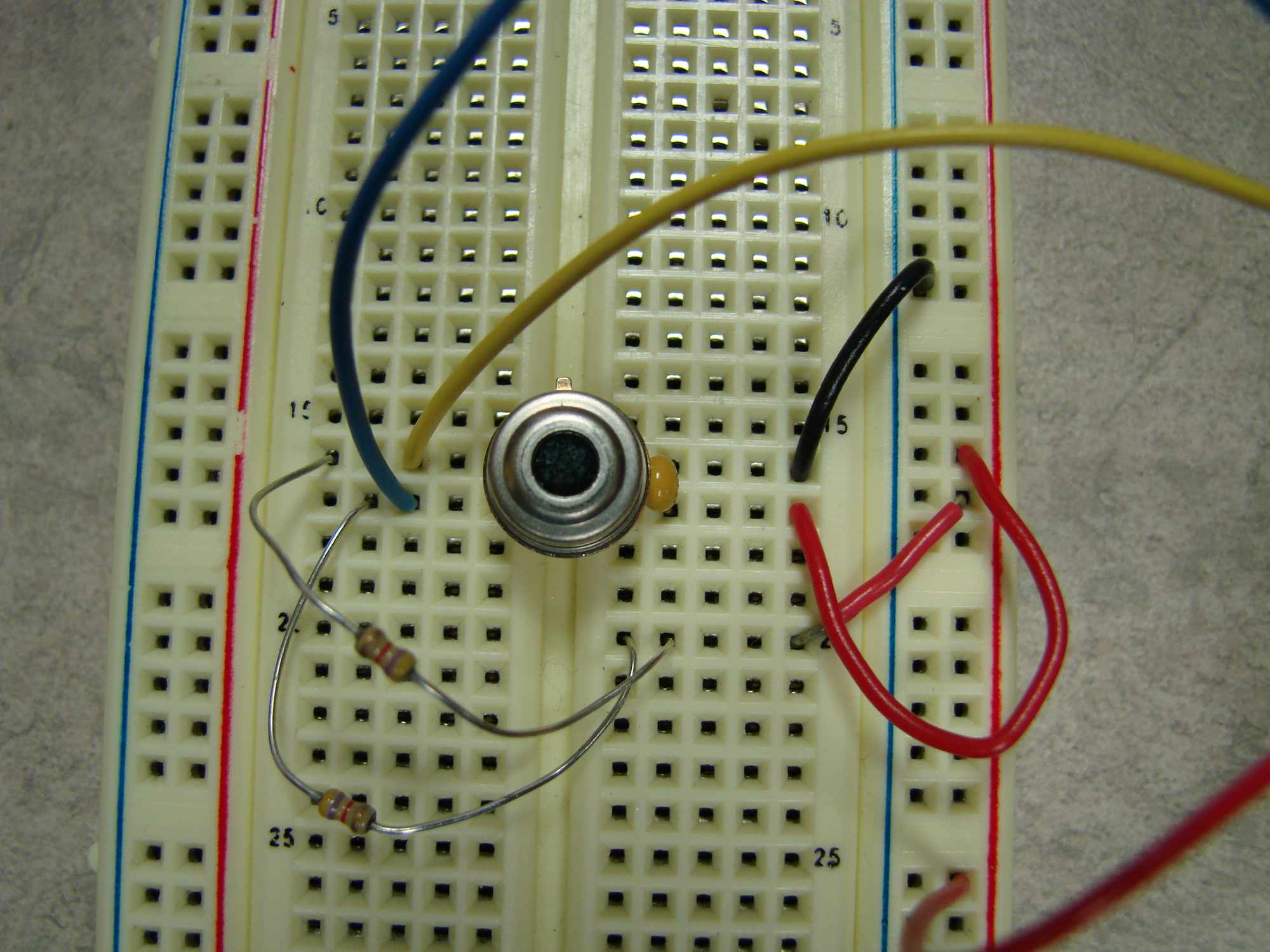
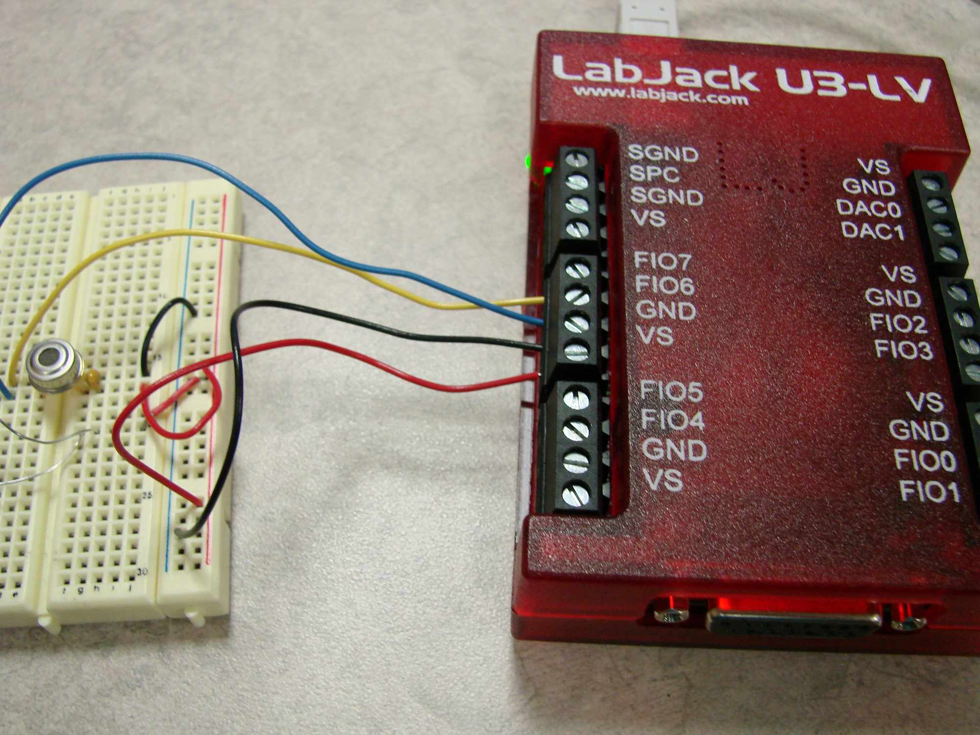
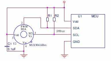
Connecting this sensor to the LabJack is a simple task; using the datasheet, you can directly connect the Vss line to GND, Vdd to VS, and the SDA/SCL to the digital lines of your choosing (for this example we used FIO6 and FIO7). Please note that our VS voltage is 5V and our FIO lines use 3.3V logic; this did not turn out to be a problem when using these sensors. The only other setup required is finding two 4.7k resistors to be used as pull up resistors for the SDA and SCL lines and installing a decoupling capacitor in between VS and GND. You can follow the schematic found on page 37 of the datasheet, figure 34 or look at the image below:
Talking to the sensor
Communicating with this sensor turned out to be quite a trick so we will start with an easy first goal, reading the temperature reported by the Tobj1 ram address. The first step in any I2C project is to find a slave address that the sensor will respond to. There is a preprogrammed 7 bit slave address of 0x5A set by the factory. However the datasheet never mentioned that the default address for this sensor is 0. If you want to configure any of the settings of the sensor you need to make sure that only one sensor is hooked up to the LabJack as all of the sensors will try and respond if there are multiple and you need to communicate with the address 0. Because of this, I recommend that if you are having problems communicating with this sensor try communicating with the zero address instead of the factory default 0x5A. After finding a valid slave address I read deeper and found out how to send information to the sensor. This information can be found in section 8.4.3 of the datasheet and is important for configuring the I2C functionality of the LabJack. In order to get information from the sensor you need to construct a packet that looks like the Read Word example transmission:
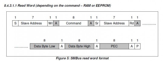
Analyzing this picture you can find that there is no space between the ACK bit after the first command and the start bit of the second slave address transmission. This tells you that you need to enable the "No stop When Restarting" feature of the LabJack. This image also tells you how to communicate with the sensor you need to write one byte of information to the sensor followed by reading 3 bytes of information. The next step is to look in the datasheet and find command bytes that can be sent which can be found in sections 8.3.3 for EEPROM Addresses and 8.3.4 for RAM Addresses. After you have figured out all of this information, you are now ready to begin writing code to communicate with the sensor:
Pseudocode
//configure the I2C transmission, communicate with the 0x0h address, SCLpin = 7, SDApin = 6, I2Coptions = 4, SpeedAdjust = 0<
AddRequest(lngHandle, LJ_ioPUT_CONFIG, LJ_chI2C_ADDRESS_BYTE, 0, 0, 0);
AddRequest(lngHandle, LJ_ioPUT_CONFIG, LJ_chI2C_SCL_PIN_NUM, 7,0,0);
AddRequest(lngHandle, LJ_ioPUT_CONFIG, LJ_chI2C_SDA_PIN_NUM, 6,0,0);
AddRequest(lngHandle, LJ_ioPUT_CONFIG, LJ_chI2C_OPTIONS, 4,0,0);
AddRequest(lngHandle, LJ_ioPUT_CONFIG, LJ_chI2C_SPEED_ADJUST, 0,0,0);
//The following code executes the configuration requests
GoOne(lngHandle);
//now prepare information to be sent:
numWrite = 1;
array[0]=0x7 //the memory address for Tobj1
AddRequest(lngHandle, LJ_ioI2C_COMMUNICATION, LJ_chI2C_WRITE, numWrite, array, 0);
numRead = 3;
AddRequest(lngHandle, LJ_ioI2C_COMMUNICATION, LJ_chI2C_READ, numRead, array, 0);
//Execute the requests
GoOne(lngHandle);
An example VI that does all of this and then reports the results in a readable fashion can be found here. In Python the same code for transmitting information is a one liner:
Basic I2C Example - python
#import and open the device import u6 d = u6.U6() #send & receive I2C data d.i2c(0x0, [0x7], NoStopWhenRestarting = True, NumI2CBytesToReceive = 3)
Summary
If you need help visualizing what this code is doing you can look at the I2C AppNote and the second picture showing transmission data. Instead of communicating with the address 0x21, we are talking to 0x0, and instead of sending the byte 0x41 we are sending 0x7. Applying this code to other functions for this sensor is also extremely easy, if you are trying to communicate with several sensors connected over I2C simply make sure that you are communicating with the proper slave address and start transmitting data. If you wish to read other addresses simply change the command byte to the address of your choice. Another important piece of information that can be found by searching Google for a while is in regards to reading EEPROM addresses. I couldn't find where in the datasheet this was explained, but if you wish to properly read settings from the EEPROM you need to add 0x20 to the EEPROM address in the table. Example: 0x02 becomes 0x22 and 0x1C becomes 0x3C.
A convenient table that you can use to read information from the sensor:
|
Name |
Address |
Location |
|---|---|---|
|
TA |
0x6 |
RAM |
|
Tobj1 |
0x7 |
RAM |
|
Tobj2 |
0x8 |
RAM |
|
ToMax |
0x20 |
EEPROM |
|
ToMin |
0x21 |
EEPROM |
|
PWMCTRL |
0x22 |
EEPROM |
|
Ta/span> |
0x23 |
EEPROM |
|
ECC |
0x24 |
EEPROM |
|
Config |
0x25 |
EEPROM |
|
Slave Address |
0x2E |
EEPROM |
Configuring the sensor
This is a more advanced use of the Melexis IR sensor therefore only attempt this if you are sure that your sensor is properly working. To write to a register on this sensor we need to follow the Write Word example transmission in the datasheet:
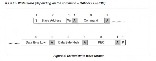
Writing to a register is done in two transmissions of data and then it is recommended that you have a final transmission where you read the address that you just wrote to in order to check if the information was written properly. When you are sure that you properly configured the register you then have to power cycle the device. This gives us four different steps:
-
Clear the address
-
Write new information to the address
-
Read the address to make sure it was set properly
-
Power cycle the sensor
Figuring out what information to send is another tricky part to this process. When ever you are trying to configure the sensor you need to communicate to the 0x0 address so you need to make sure there is only one sensor connected to the LabJack. Each write transmission will consist of four bytes of data, the first being the address that you wish to configure, the second is the LSB byte of data, the third is the MSB byte of data, and the fourth is PEC value to make sure that the data being sent is valid. The PEC value is calculated using the CRC-8algorithm, a calculator for this can be found here. I also made a LabVIEW 6.0.2 VI that calculates the value, CRC-8.vi.
Setting a goal
It is now time to figure out what we wish to configure, for this example we will set the slave address of the sensor. The example will set the 7 bit slave address to 0x4 which can be split into two bytes where 0x4 is the LSB of data and 0x0 is the MSB of data. If you look at the table earlier in this tutorial you will find that the slave address is in the EEPROM address of 0x2E (0x0E in the datasheet). You can then enter the string 2E0400 into the CRC-8 calculator and use the PEC value of 3B to finish gathering all of the necessary information. Now for the fun part, transmitting the information using a LabJack device.
Clearing the Address
To do this, we need to first get the PEC value for the transmission which will be 2E0000, 2E = EEPROM address, 00 = LSB, 00 = MSB. The PEC value that gets returned by the calculator is 6F. Therefore we can now send the array (use the same configuration's as the read transmission):
[0x2E, 0x0, 0x0, 0x6F]
numWrite = 4;
array[0]=0x2E
array[1]=0x0;
array[2]=0x0;
array[3]=0x6F;
AddRequest(lngHandle, LJ_ioI2C_COMMUNICATION, LJ_chI2C_WRITE, numWrite, array, 0);
GoOne(lngHandle);
//you then delay in order to let the sensor write the information to the EEPROM address:
delay(200ms);
In Python this can be done:
- python
d.i2c(0x0,[0x2E, 0x0, 0x0, 0x6F], NoStopWhenRestarting = True) time.sleep(200)
Setting the Address
To do this we use the information we gathered above, we need to send the array:
[0x2E, 0x04, 0x0, 0x3B]
numWrite = 4;
array[0]=0x2E
array[1]=0x04;
array[2]=0x0;
array[3]=0x3B;
AddRequest(lngHandle, LJ_ioI2C_COMMUNICATION, LJ_chI2C_WRITE, numWrite, array, 0);
GoOne(lngHandle);
//you then delay in order to let the sensor write the information to the EEPROM address:
delay(200ms);
In Python this can be done:
- python
d.i2c(0x0,[0x2E, 0x04, 0x0, 0x3B], NoStopWhenRestarting = True) time.sleep(200)
Read the Address
To do this we repeat the steps from the talking to the sensor section keeping in mind that we only need to configure the sensor once when using LabVIEW and our high-level driver. Using lower level commands like Python, everything is bunched into one command so this is not applicable. Simply read from the 0x0 address again and instead of sending 0x7 send 0x2E. The LSB response should be the slave address that you wrote to the sensor. If it isn't you transmitted the wrong information to the sensor and you should avoid power cycling the device and try again.
Power Cycle the Sensor
To get the information you just wrote to the sensor to be used you need to power cycle the sensor.
Test your configuration
To test to make sure you properly changed the slave address try reading temperatures from it. Convert the 7 bit slave address that you wrote to the device to an 8 bit address (address<<1, 0x4 becomes 0x8). Set the Address by reconfiguring the I2C configurations:
//configure the I2C transmission, communicate with the 0x8h address, SCLpin = 7, SDApin = 6, I2Coptions = 4, SpeedAdjust = 0
AddRequest(lngHandle, LJ_ioPUT_CONFIG, LJ_chI2C_ADDRESS_BYTE, 8, 0, 0);
AddRequest(lngHandle, LJ_ioPUT_CONFIG, LJ_chI2C_SCL_PIN_NUM, 7,0,0);
AddRequest(lngHandle, LJ_ioPUT_CONFIG, LJ_chI2C_SDA_PIN_NUM, 6,0,0);
AddRequest(lngHandle, LJ_ioPUT_CONFIG, LJ_chI2C_OPTIONS, 4,0,0);
AddRequest(lngHandle, LJ_ioPUT_CONFIG, LJ_chI2C_SPEED_ADJUST, 0,0,0);<
//The following code executes the configuration requests
GoOne(lngHandle);
//Now read from the sensor at the new address:
numWrite = 1;
array[0]=0x7 //the memory address for Tobj1
AddRequest(lngHandle, LJ_ioI2C_COMMUNICATION, LJ_chI2C_WRITE, numWrite, array, 0);
numRead = 3;
AddRequest(lngHandle, LJ_ioI2C_COMMUNICATION, LJ_chI2C_READ, numRead, array, 0);
//Execute the requests
GoOne(lngHandle);
//or in Python:
d.i2c(0x4, [0x7], NoStopWhenRestarting = True, NumI2CBytesToReceive = 3)
Please note that in Python we automatically convert a 7 bit address to an 8 bit one, so you don't have to do this yourself. There is an example VI that you can download that does all of this and works with our U3, U6 and UE9 devices and can be found here. Note this VI requires the CRC-8.vi the link is for a .zip file instead.
Summary
After you have gotten all of these examples to work you can now fully utilize this sensor in your next project. A nice all inclusive utility to use this sensor can be found here. Change what device you wish to use in the "Configure Available Addresses/Program tab" and have fun!