This AppNote explains the operation and use of the I2C functionality of our LabJack devices with special regards to the Honeywell HMC6352 Magnetometer.
Overview of I2C
The basis of I2C with regards to our devices is a two wire serial interface that lets you communicate to sensors or embedded systems that require a host device to properly function. The host device is initially in transmit mode and sends a start bit followed by a 7-bit address of the slave it wishes to communicate with which is followed by a single bit representing whether it wishes to write(0) or read (1) from the slave. If the slave exists on the buss then it will respond with an ACK bit for that address and the master then continues in either transmit or receive mode and the slave continues in its complementary mode. If the master wishes to write to the slave then it repeatedly sends a byte of information with the slave sending an ACK bit in response. If the master wishes to read from the slave then it repeatedly receives a byte of information from the slave and sending back an ACK bit for every byte but the last one. Once communication is finished, the data transmission concludes with a stop bit. A quick look at what these waveforms will look like, you can reference page 4 and 9 of the datasheet for the HMC6352 that we will be using: HMC6352.pdf.
Using a LabJack as the Master
Before attempting communication with a I2C slave through a LabJack, insure the following conditions are met:
-
The slave must accept 3.3V logic as that is the voltage of our FIO, CIO, and EIO lines.
-
If connecting to VS on the device, make sure that the slave accepts 5V as a supply voltage, if it doesn't then another power supply, a regulator, or a DAC (if the sensor’s current requirement is sufficiently low), will be needed.
-
Make sure that the correct pull-up resistors are installed, refer to the device datasheet for appropriate conditions.
After the above conditions are met, it will be possible to initiate communication with I2C slaves using a LabJack as the master.
Using a LabJack as the Master
The low-level function for I2C requires that you can supply it with a valid address that needs to be communicated with, a list of bytes that need to be sent to that address. You can also specify how many bytes will be received, what pins to use as SCL and SDA and other attributes as defined in the I2C function reference.
Example (UE9/U6/U3 Compatible)
Overview
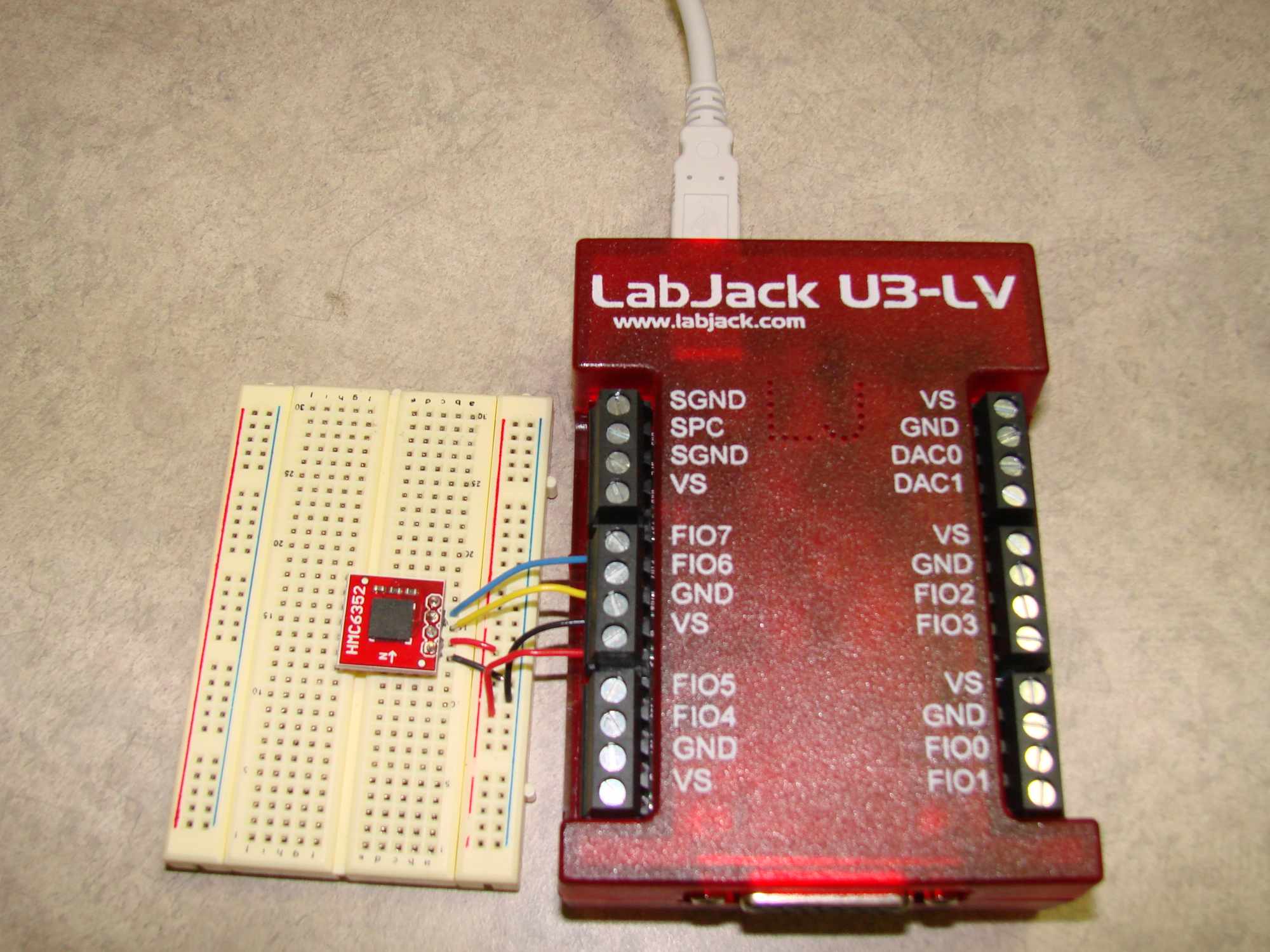
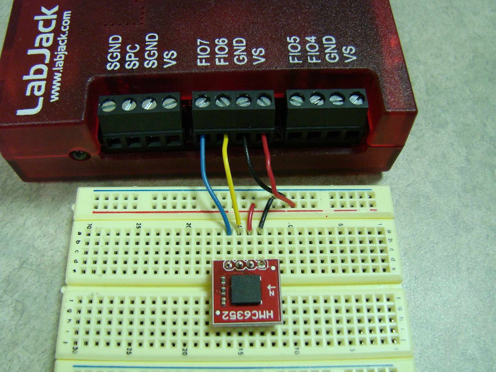
For this example a Honeywell HMC6352 digital magnetometer(obsolete) is used to demonstrate the use of I2C. The U3-LV running firmware v1.24 is configured as the master and the Magnetometer has been soldered to a break out board exposing the SCL SDA VS and GND pins. Above is a picture of this test setup.
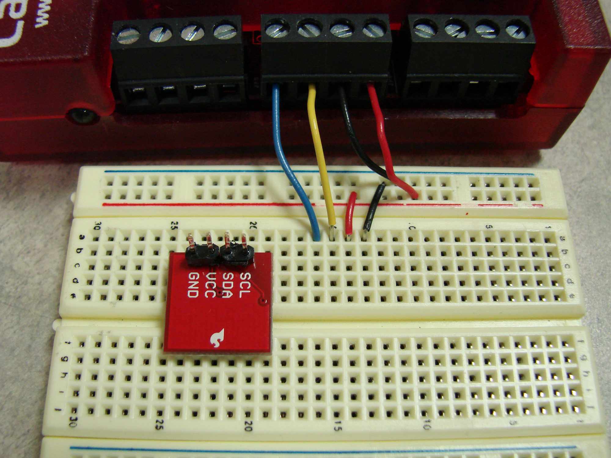
Connections
Since 5V(VS) is readily available on the U3-LV and the digital Magnetometer is capable of using 5V as an input voltage and there are already pull-up resistors and a decoupling capacitor installed on the included break out board by SparkFun, all that is left to do is connect the device to the LabJack. As the picture above shows, the SCL line was connected to FIO7, the SDA line was connected to FIO6, VCC to VS, and GND to GND.
Initiating Communication
The first step in communicating to the HMC6352 and other I2C devices is figuring out what I2C address the device will respond to. This information can all be found by looking at its datasheet:HMC6352.pdf. The specific information were looking for at this time is found on page 3, the address that we need to communicate with to write information to the device is 0x42 and to read it is 0x43.
The Command Byte
The second step in communicating to the HMC6352 is figuring out what information to send to the device. Most of this information can be found at the top of page 5 of the datasheet in table 1. The command byte, A(41) is what we will send the Magnetometer to get a response that pertains to what direction it is facing. To send the Magnetometer other requests, simply change the command byte to a different recognized command, and add bytes after (if needed) when building the list of bytes, shown later.
Predicting the response and interpretation
In order to get useful information from the Magnetometer the U3 needs to be told how many bytes of information it needs to receive to get a complete amount of information. This can be found by looking at the same table that was used to find a list of valid commands. Looking closely, the command 0x41 requires that we listen for a two byte response, Response 1, the MSB of data; and Response 2, the LSB of data. These groups of information can be combined into one long binary response that can be interpreted as tenths of degrees from zero to 3599 (page 7 of the datasheet, under the title Heading Mode).
Useful Code
The following download is a python example program that was created during testing of this HMC6352 Magnetometer and can be used as a reference to develop for additional I2Ccompatibleslave devices.
HMC6352.py_.txt(you will need to re-name the file to HMC6352.py in order to run the example)
Problems and Troubleshooting
The first problem that was encountered was that the I2C command doesn't configure the device to digital output. I found this problem when trying to use the FIO4 and FIO5 lines instead of the default FIO6 and FIO7 lines. The device I was using had FIO4 configured to be a clock output line. To quickly fix this problem, the following line sets all FIO and EIO lines to digital lines:
d.configIO(FIOAnalog = 0, EIOAnalog = 0)
A common problem is passing the wrong I2C address to our API. In the LabJackPython I, You should pass in the 7-bit I2C address. The address passed in is shifted over one bit, so if you tell it to write to the address 0x42, it writes the address 0x84.
A useful troubleshooting step is to set the internal LabJackPython debug value to true, d.debug = True, which tells the library to print out useful debug information. Using the debug information, you can look at each of the bytes that was being sent. The 11th byte is the address byte as defined by the low-level I2C function description.