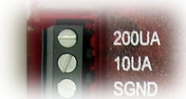
The T7 has 2 fixed current source terminals useful for measuring resistance (thermistors, RTDs, resistors). The 10UA terminal provides approximately 10 µA and the 200UA terminal provides approximately 200 µA, but the actual values should be read from the calibration constants, or better yet measured in real-time using a fixed shunt resistor.
Using the equation V=IR, with a known current and voltage, it is possible to calculate the resistance of the item in question. Figure 12-1 shows a simple setup measuring 1 resistor.
The factory value of each current source is noted during calibration and stored with the calibration constants on the device. These can be viewed using the Device Info tab in Kipling, or read programmatically. Note that these are fixed constants stored during calibration, not some sort of real-time readings.
To read the constants, read from the following registers:
Example:
To read the factory value of the 200uA current source, perform a read of Modbus address 1902, and the result would be in the form of a floating point number, e.g. 0.000197456 amps.
Examples Of Measuring Resistance
Multiple resistances can be measured by putting them in series and measuring the voltage across each. Some applications might need to use differential inputs to measure the voltage across each resistor, but for many applications it works just as well to measure the single-ended voltage at the top of each resistor and subtract in software.
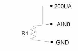
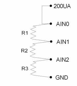
Figure 12-1 shows a simple setup measuring 1 resistor. If R1=3k, the voltage at AIN0 will be 0.6 volts.
Figure 12-2 shows a setup to measure 3 resistors using single-ended analog inputs. If R1=R2=R3=3k, the voltages at AIN0/AIN1/AIN2 will be 1.8/1.2/0.6 volts. That means AIN0 and AIN1 would be measured with the ±10 volt range, while AIN2 could be measured with the ±1 volt range. This points out a potential advantage to differential measurements, as the differential voltage across R1 and R2 could be measured with the ±1 volt range, providing better resolution.
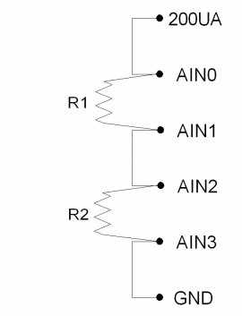
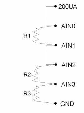
Figure 12-3 shows a setup to measure 2 resistors using differential analog inputs. AIN3 is wasted in this case, as it is connected to ground, so a differential measurement of AIN2-AIN3 is the same as a single-ended measurement of AIN2. That leads to Figure 12-4, which shows R1 and R2 measured differentially and R3 measured single-ended.
Remarks
Maximum load resistance: The current sources can drive about 3 volts max, thus limiting the maximum load resistance to about 300 kΩ (10UA) and 15 kΩ (200UA). Keep in mind that high source resistance could cause settling issues for analog inputs.
Using a fixed resistor to calculate actual current: For some applications the accuracy and temperature coefficient of the current sources is sufficient, but for improvement a fixed resistor can be used as one of the resistors in the figures above. The Y1453-100 and Y1453-1.0K from Digi-Key have excellent accuracy and very low tempco. By measuring the voltage across one of these you can calculate the actual current at any time.
Handling load changes resulting in noise: The current sources are not particularly fast in reacting to load changes. This can show up as noise when rapidly sampling multiple channels using the same current source. Improve behavior by adding a 1 µF ceramic capacitor from the current source to GND and/or increasing settling time.
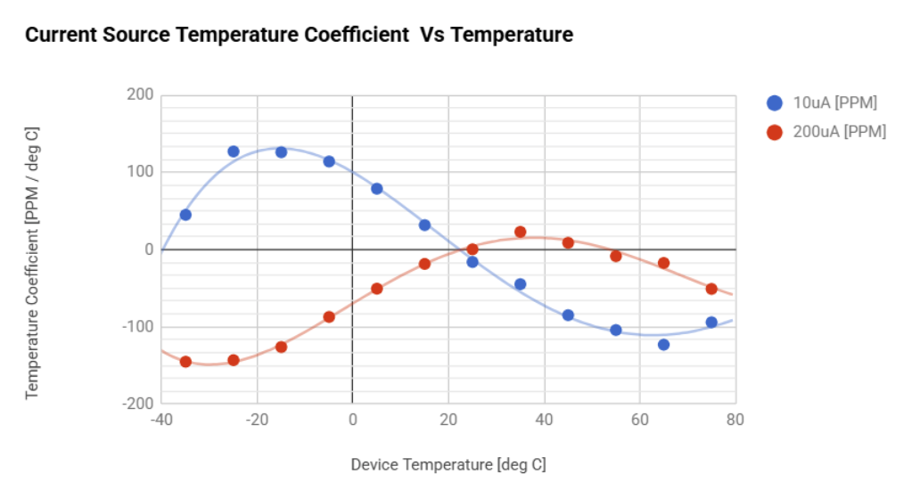
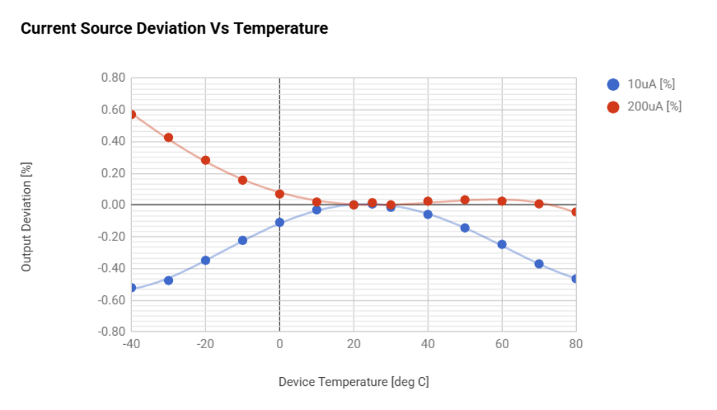
Temperature coefficients: Figures 12-5 and 12-6 show the typical current source output variation over temperature. Both sources typically have low temperature coefficients at or near 25C. Beyond 25C, the temperature coefficient variation may need to be accounted for, depending on application requirements.
Examples