Overview
AIN-EF indices that need to measure resistance (Resistance, RTD, Thermistor) can use different types of excitation circuits. The excitation circuit converts the varying resistance to a voltage signal that can be measured by the LabJack.
Individual AIN-EF indices may only support a subset of the circuits listed here.
For AIN-EF indices that require excitation circuits, the circuit indices below are written to AIN#_EF_CONFIG_B.
The most commonly used circuit is #4, as it is designed for the LJTick-Resistor.
These circuits all use a voltage source or current source for excitation. Note that any noise in the excitation source will result in proportionate noise in the sensor signal. Sources designed for excitation (e.g. voltage reference) are recommended rather than power supplies (e.g. VS).
Current Source Excitation Circuits
The first 3 excitation circuits are specific to current source excitation. A current source varies voltage so it can provide the specified fixed current.
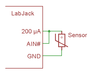
Circuit 0 – 200 µA Current Source - T7:
This excitation circuit uses the 200 µA current source available on the T7 to excite a sensor. It calculates resistance based on the measured voltage and the stored factory calibration value for 200UA. This circuit is useful for smaller resistances such as RTDs.
The following figure shows a basic single sensor connection, but if the AIN is configured and connected as differential, multiple sensors can be put in series as shown in figures from the 200UA/10UA documentation.
Configuration registers:
-
AIN#_EF_CONFIG_C - Ignored
-
AIN#_EF_CONFIG_D - Ignored
-
AIN#_EF_CONFIG_E - Ignored
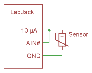
Circuit 1 – 10 µA Current Source - T7:
This excitation circuit uses the 10 µA current source available on the T7 to excite a sensor. It calculates resistance based on the measured voltage and the stored factory calibration value for 10UA. This circuit is useful for larger resistances such as thermistors.
The following figure shows a basic single sensor connection, but if the AIN is configured and connected as differential, multiple sensors can be put in series as shown in figures from the 200UA/10UA documentation.
Configuration registers:
-
AIN#_EF_CONFIG_C - Ignored
-
AIN#_EF_CONFIG_D - Ignored
-
AIN#_EF_CONFIG_E - Ignored
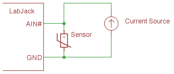
Circuit 2 – Custom Current Source:
This excitation circuit uses a current source external to the LabJack. The current provided by the source is specified during configuration of the AIN#_EF.
The following figure shows a basic single sensor connection, but if the AIN is configured and connected as differential, multiple sensors can be put in series.
Configuration registers:
-
AIN#_EF_CONFIG_C - Ignored
-
AIN#_EF_CONFIG_D - Excitation Amps
-
AIN#_EF_CONFIG_E - Ignored
Resistive Divider Excitation Circuits
Divider circuits rely on an excitation source and a fixed resistor in series with the sensor.
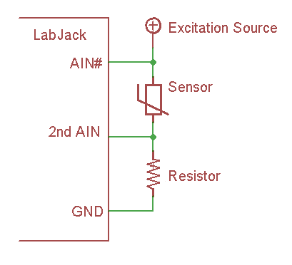
Circuit 3 – Divider with Measured Excitation - Differential:
This circuit has an excitation source in series with a sensor which is then in series with a fixed resistor to ground. The device takes the single-ended reading of 2ndAIN to get Vresistor, and takes the differential reading of AIN# to get Vsensor. Vresistor is divided by the specified fixed resistance to get current, and then Vsensor is divided by that current to get the resistance of the sensor.
The drawing shows the most common way of connecting. AIN# is a positive differential channel (e.g. AIN2) and 2ndAIN is the negative associated with that channel (e.g. AIN3). Alternatively, any differential pair of analog inputs can be connected across the sensor, and 2ndAIN can be any single-ended analog input. This allows multiple sensors to be connected in series with a single excitation source.
AIN# must be pre-configured by the user as differential or an error will be thrown. Thus this circuit is supported on the T7 but not the T4.
Configuration registers:
-
AIN#_EF_CONFIG_C - 2nd AIN: Channel Number to Measure Vresistor
-
AIN#_EF_CONFIG_D - Ignored
-
AIN#_EF_CONFIG_E - Fixed Resistor Ohms
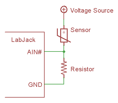
Circuit 4 – Voltage Source with Specified Value:
This excitation circuit uses a voltage source and a shunt resistor. Values for the output of the voltage source and the resistor must be provided during AIN#_EF configuration. When using this circuit, the LabJack will measure the voltage between the sensor and the resistor, then calculate the resistance of the sensor.
Configuration registers:
-
AIN#_EF_CONFIG_C - Ignored
-
AIN#_EF_CONFIG_D - Excitation Volts
-
AIN#_EF_CONFIG_E - Fixed Resistor Ohms.
Note for the LJTick-Resistance: This excitation circuit #4 is the most common circuit used with the LJTick-Resistance. The "Resistor" shown above is built into the LJTick-Resistance, so to create this circuit simply connect one side of the RTD to LJTR-Vref and the other side of the RTD to LJTR-VINx.
Note for the T8: The T8 has two 3.3 V reference voltage outputs that could be suitable for excitation.
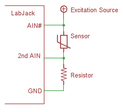
Circuit 5 – Divider with Measured Excitation - Single-Ended:
This circuit has an excitation source in series with a sensor which is then in series with a fixed resistor to ground. The device takes the single-ended reading of 2ndAIN to get Vresistor, and takes the single-ended reading of AIN# minus the reading from 2ndAIN to get Vsensor. Vresistor is divided by the specified resistance to get current, and then Vsensor is divided by current to get the resistance of the sensor.
Must be connected exactly as shown in the drawing. AIN# and 2ndAIN can be any channels.
This excitation circuit looks the same as circuit #3, but the voltage across the sensor is determined by the difference of 2 single-ended readings rather than a single differential reading. That means this circuit is supported on all devices and is limited to a single sensor in series with the excitation source.
Configuration registers:
-
AIN#_EF_CONFIG_C - 2nd AIN: Channel Number to Measure Vresistor
-
AIN#_EF_CONFIG_D - Ignored
-
AIN#_EF_CONFIG_E - Fixed Resistor Ohms
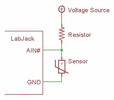
Circuit 1004 – Voltage Source with Specified Value (swapped fixed resistor position) - T4/T7
This excitation circuit uses a voltage source and a shunt resistor. It is the same as circuit 4 except with the fixed resistor and sensor positions swapped. Values for the output of the voltage source and the resistor must be provided during AIN#_EF configuration. When using this circuit, the LabJack will measure the voltage between the sensor and the resistor, then calculate the resistance of the sensor.
Configuration registers:
-
AIN#_EF_CONFIG_C - Ignored
-
AIN#_EF_CONFIG_D - Excitation Volts
-
AIN#_EF_CONFIG_E - Fixed Resistor Ohms.
Note for the T8: The T8 has two 3.3 V reference voltage outputs that could be suitable for excitation.
