Number of Pins: 37
Screw type: #4-40
Contacts: Gold-coated
Form factor: D-Sub
This high-density female DB37 connector provides access to T7 features that are not available on the screw terminal edge of the unit. It brings out analog inputs (AIN), analog outputs (DAC), digital I/O (FIO, MIO), and other signals.
The CB37 is a connector board that provides convenient screw-terminals for the DB37 lines, but the CB37 is not required to access I/O on the DB37. Any method you see fit can be used to access the DB37 lines.
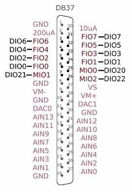
Pinout
Some signals appear on both the DB37 connector and screw terminals, so care must be taken to avoid contention. For such signals, only connect to one location, not both. Signals duplicated on the T7 screw terminals and the DB37 are denoted in bold:
Table 16-1. DB37 Connector Pinouts
|
1 |
GND |
|
20 |
10 µA |
|
2 |
200 µA |
|
21 |
FIO7 |
|
3 |
FIO6 |
|
22 |
FIO5 |
|
4 |
FIO4 |
|
23 |
FIO3 |
|
5 |
FIO2 |
|
24 |
FIO1 |
|
6 |
FIO0 |
|
25 |
MIO0 |
|
7 |
MIO1 |
|
26 |
MIO2 |
|
8 |
GND |
|
27 |
VS |
|
9 |
VM- |
|
28 |
VM+ |
|
10 |
GND |
|
29 |
DAC1 |
|
11 |
DAC0 |
|
30 |
GND |
|
12 |
AIN13 |
|
31 |
AIN12 |
|
13 |
AIN11 |
|
32 |
AIN10 |
|
14 |
AIN9 |
|
33 |
AIN8 |
|
15 |
AIN7 |
|
34 |
AIN6 |
|
16 |
AIN5 |
|
35 |
AIN4 |
|
17 |
AIN3 |
|
36 |
AIN2 |
|
18 |
AIN1 |
|
37 |
AIN0 |
|
19 |
GND |
|
|
|
Remarks
VS, GND, FIO/MIO, AIN, DAC, 200UA/10UA
Descriptions of these can be found in their related sections of this datasheet.
VM+/VM-
Vm+/Vm- are bipolar power supplies intended to power external multiplexer ICs such as the DG408 from Intersil. The multiplexers can only pass signals within their power supply range, so Vm+/Vm- can be used to pass bipolar signals. Nominal voltage is ±13 volts at no load and ±12 volts at 2.5 mA. Both lines have a 100 ohm source impedance, and are designed to provide 2.5 mA or less. This is the same voltage supply used internally by the T7 to bias the analog input amplifier and multiplexers. If this supply is loaded more than 2.5 mA, the voltage can droop to the point that the maximum analog input range is reduced. If this supply is severely overloaded (e.g. short circuited), then damage could eventually occur. If Vm+/Vm- are used to power multiplexers, series diodes are recommended as shown in Figure 9 of the Intersil DG408 datasheet. Not so much to protect the mux chips, but to prevent current from going back into Vm+/Vm-. Use Schottky diodes to minimize voltage drop.
Duplicated Input Terminals (AIN0-AIN3 and FIO0-FIO3)
AIN0-AIN3 and FIO0-FIO3 appear on the built-in screw-terminals and also on the DB37 connector. You should only connect to one or the other, not both at the same time.
To prevent damage due to accidental short circuit, both connection paths have their own series resistor.
All FIO lines have a 470 ohm series resistor (that is included in the 550 ohm total impedance), and in the case of FIO0-FIO3 the duplicated connections each have their own series resistor, so if you measure the resistance between the duplicate terminals you will see about 940 ohms.
All AIN lines have a 2.2k series resistor, and in the case of AIN0-AIN3 the duplicated connections each have their own series resistor, so if you measure the resistance between the duplicate terminals you will see about 4.4k.
CB37 Terminal Board
The CB37 terminal board from LabJack connects to the DB37 connector and provides convenient screw terminal access to all lines. The CB37 is designed to connect directly to the DB37, but can also connect via a 37-line 1:1 male-female cable.
When using the analog connections on the CB37, the effect of ground currents should be considered, particularly when a cable is used and substantial current is sourced/sunk through the CB37 terminals. When any sizable cable lengths are involved, a good practice is to separate current carrying ground from ADC reference ground. An easy way to do this on the CB37 is to use GND as the current source/sink, and use AGND as the reference ground. This works well for passive sensors (no power supply), such as a thermocouple, where the only ground current is the return of the input bias current of the analog input.
OEM
The OEM T7 has a separate header location to bring out the same connections as the DB37 connector. This OEM header location is labeled J3. The J3 holes are always present, but are obstructed when the DB37 connector is installed. Find the pinout, and other OEM information for J3 in OEM Versions.