22.0 OEM Versions [T-Series Datasheet]
Overview
The OEM versions of the T-Series devices are designed for easy customization of the connection ports with pin-headers for integration into larger systems. To reduce price:
OEM versions of devices are sold without cases, cables, and other accessories.
OEM versions of devices are manufactured without screw terminals and the DB15 and DB37 connectors.
Ordering
For pricing/ordering, select the appropriate OEM variant:
Customization:
Custom OEM boards carry additional cost, but they are often necessary for specialized enclosures and seamless integration with other products. LabJack offers a device customization service that allows for OEM devices to be ordered with custom parts installed prior to shipping. For small quantities LabJack can customize boards in house, for larger quantites we will ask our CM to perform the customizations. LabJack also re-calibrates and tests the device after performing the modifications to ensure the devices are still working properly before shipping.
For customization, please send us an email or contact us—we will most likely need to generate a custom quote and order to fulfill and bill against. Please don't hesitate to contact us.
Once order is placed all Customizations are NCNR (Non-Cancellable non-Refundable) with no scheduled changes.
Lead Time: Custom OEM board lead times currently vary from a few weeks to 6+ months depending on complexity, production schedule, part availability, quantity, etc. contact us for an exact quote and lead time based on your specific build and application.
Pinouts
The OEM versions of T-series devices are shown below, with the pinouts of the (T4) H2, H3, J2, J5 and (T7) J2, J3, J5 connectors:
T4-OEM:
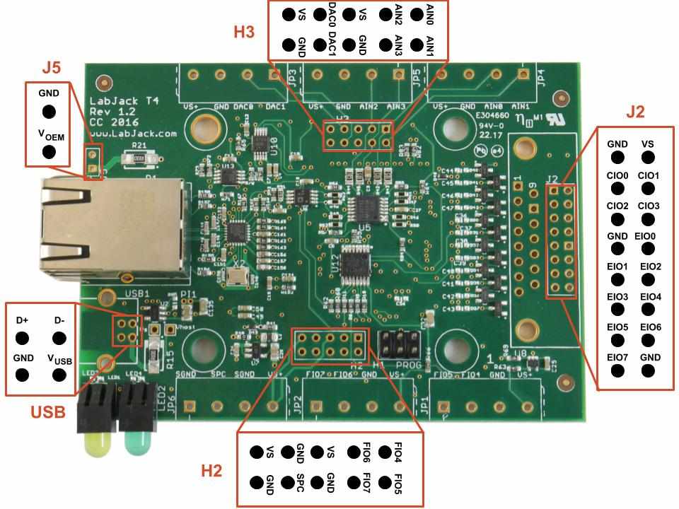
The T4-OEM exposes all of its I/O lines through the pin-headers H2, H3, and J2. The device can be externally powered with a regulated 5V supply using the J5 connector. If needed, a USB connector can also be installed—see the USB section below. More details about the PCB dimensions can be found in Appendix B-2 T4 Enclosure and PCB Drawings.
T7-OEM and T7-Pro-OEM:
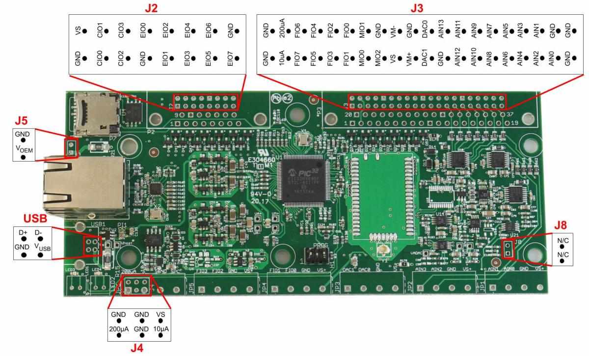
Image 22-2. T7-OEM Pinout
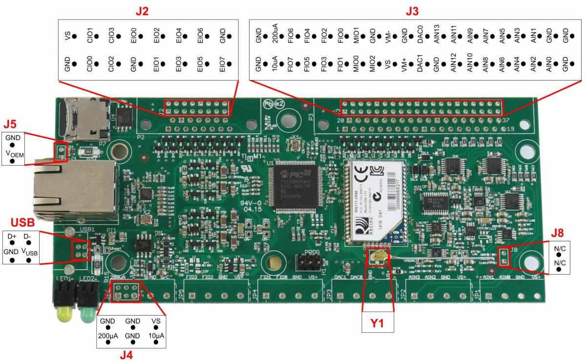
Image 22-3. T7-Pro-OEM Pinout
The T7-OEM and T7-Pro-OEM devices expose all of their I/O lines through the J2 and J3 pin-header locations. Both devices can be externally powered with a regulated 5V supply using the J5 connector. If needed, a USB connector can also be installed—see the USB section below. More details about the PCB dimensions can be found in Appendix B-2 T7 Enclosure and PCB Drawings.
Suggested Part Orientations: We suggest that customers install pin headers on the top side of our devices to prevent there from being any issues with device re-calibration. During the calibration process, our OEM devices are mounted to the top of our test jigs (pogo pins make contact with the holes on the bottom side). Our device-calibration test jigs use a combination of the screw terminal holes as well as the DB15 and DB37 holes to test each of the I/O lines.
Pin-Headers: The T4 and T7 OEM devices have pin-outs compatible with pin-headers that have a pin pitch of 0.100" (2.54mm). Below is a list of the standard pin-headers that we install into the J2, J3, J5, H2, and H3 locations. Other parts can be installed upon request including shrouded or directional pin-headers.
Table 22-1. Pin-Headers
Name | Pins | Parts |
|---|---|---|
J5 | 1x2 | |
H2 and H3 | 2x5 | |
J2 | 2x8 | |
J3 | 2x20 |
PCB Dimensions: The PCB dimensions and a variety of mechanical drawings can be found in the Enclosure and PCB Drawings section of the T-Series datasheet.
ESD: Proper ESD precautions should be taken when handling the PCB directly. Many of the parts are ESD-resistant, but depending on the size or location of the shock, the board might be damaged.
Part Categories: Optional parts that can be installed can be broken down into the following categories:
USB
The USB connector is not installed on any of the T-Series OEM devices. The T-Series devices use through-hole Type-B connectors and there are a large number of compatible connectors.
Mounting Location: The USB connector must be installed on the component side of the PCB.
Suggested Parts: We have several suggested USB connectors, however, most USB Type-B through hole connectors are compatible with the T-Series OEM devices. Standard retention USB connectors are installed on all LabJack DAQ devices and are enough for most OEM device applications. High-retention USB connectors are higher in cost, however, they more securely connect a USB cable to a device, which is important in many industrial applications.
Horizontal Mount
Standard Retention | High Retention |
|---|---|
USB Pin-Out: The pictures below show the bottom side of T-series devices and indicate the purpose of the four USB pins. Pin-outs relative to the top side are documented in the pinout pictures above.
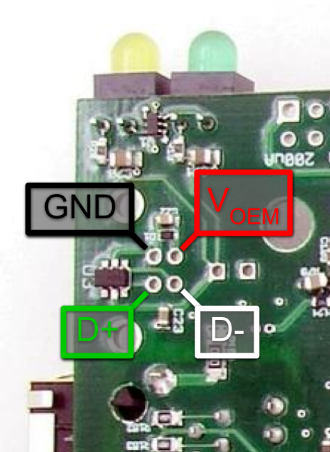
Image 22-4. T7 USB Pinout
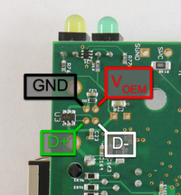
Image 22-5.T4 USB Pinout
USB Cables: A normal USB cable has a shield, and the normal Type-B connector connects the cable shield to the mounting tabs on the connector which are then soldered into the large USB mounting holes on the PCB. If you are not using a normal USB connector and have a shield in your USB cable, we recommend that the shield be connected to either of the large USB mounting holes on the PCB. Usually the USB shield wires are aluminum—which don't take solder very well—so use a crimp connector like the Molex 02-06-2103, TE 61388-1, TE 350015-2, or the TE 60017-3. Secure the crimp connector to USB shield wires, then squish down the tip of the connector to fit into the large USB mounting holes on the PCB.
To connect to a device without USB, you can use a direct Ethernet connection. Use an SPC-to-AIN3 jumper to temporarily configure a static IP.
Alternate Power Supply (J5)
T-Series OEM devices can be powered through a few different connectors such asthe J5 pin-header holes. The J5 pin-header is useful for applications that only need Ethernet or WiFi device connections. The square shaped pad of the J5 pin-header is V+ and the circular pad is GND. The J5 connector is a 2-pin 0.1" pitch rectangular header. To prevent accidentally switching V+ and GND, use a keyed connector such as TE Connectivity 3-641215-2.
All device power supply options require a 5V input voltage. See the power supply input section of Appendix-A-5 for detailed specs.
T4, T7
The T4 and T7 only support power via USB and power via the J5 power headers (VS-OEM below).
Image 22-6. T4/T7 Power Supply
The 5V supply from J5 (J5-VS) is protected by a TVS (transient voltage suppressor diode D2), then goes through R21 (0.1 ohms), and then connects to the internal Vsupply rail.
The 5V supply from the USB (USB-VS) is exposed through a test point on the PCB labeled Vhost and is protected by the TVS diode D1 and R15 (0.1 ohms) before connecting to the internal Vsupply rail.
The internal Vsupply rail can be measured using the test point on the PCB labeled Vs. After joining, power flows through a current limiting chip (currently the Diodes AP2141WG) and an EMIFIL (EMI suppression filter) before connecting to the device-wide VS bus and out to each of the screw terminals labeled as VS.
Dual Power Supply: R15 and R21 are installed by default and thus the connections for both sources are essentially shorted to each other. Both power supply options should not be connected to a voltage source at the same time. If this happens, one power supply could back-feed the other which may cause damage. If a device is going to be powered using the J5 connector and there is a possibility of power at the USB connection (and USB power is not required) then it is recommended to remove R15 so that only the J5 pin-header is used to power the device. If a dual-power supply method is required, it is recommended to replace the R15 and R21 resistors with Schottky diodes (SMA package). There will still be a small voltage drop that needs to be considered but the device should operate correctly as long as the voltage present on the VS screw terminals is above 4.75V (reference).
T8
The T8 OEM is not kept in regular stock. If you require an OEM version, please reach out to support@labjack.com for assistance.
The default configuration of the T8 has two power supply options, USB and PoE (Power over Ethernet). The PoE side is always prioritized; when the PoE exceeds a voltage threshold, that power supply will be used regardless of the voltage on the other supply. The same prioritization system is applied when using J5 (VOEM in image 22-7). If J5 replaces the PoE it will be prioritized. If J5 replaces USB then PoE will still be prioritized.
To configure the T8 for the desired power selection, a few resistors need to be installed or removed. Power supply configurations are:
Configuration | R15 | R21 | R86 | R87 |
|---|---|---|---|---|
USB and PoE-prioritized | Installed | Not Installed | Not Installed | Installed |
USB and J5-prioritized | Installed | Not Installed | Installed | Not Installed |
J5 and PoE-prioritized | Not Installed | Installed | Not Installed | Installed |
More than Two Power Supplies: If both R15 and R21 or R86 and R87 are installed, then some of the power supplies will be shorted together. Shorted power supplies should not be connected to a voltage source at the same time. If this happens one power supply could back-feed the other, which may cause damage.
Image 22-7. T8 Power Circuitry
DB15 and DB37 equivalent Pin-Header Locations (J2, J3)
Connectors J2 and J3 provide pin-header alternatives to the DB15 and DB37 connectors. The J2 and J3 holes are always present, but are obstructed when the DB15 and DB37 are installed.
The T4-OEM only has the J2 header.
The T7-OEM and T7-Pro-OEM both have the J2 and J3 headers.
J2 and J3 can be seen in the pictures at the top of this page which show the component side of each of the T-Series device PCBs. For both the DBs and pin headers, holes with a square solder pad indicate pin number 1, 10, 20, or 30. For both the DBs and pin headers, pin 1 is at the lower-left. For the DB connectors the pin numbers increment from 1 left to right across the bottom row, and then continue left to right across the top row. For the pin headers, the odd pins increment left to right across the bottom row (1, 3, 5, ...) and the even pins increment left to right across the top row (2, 4, 6, ...).
J2 - 16 position, 2 row, 0.1" pitch, male pin rectangular header
Unshrouded - Harwin Inc M20-9980846
Unshrouded 3x Taller - Samtec Inc TSW-108-17-T-D
Shrouded, Gold Finish - On Shore Technology Inc 302-S161
Shrouded, Right Angle - TE Connectivity 1-1634689-6
J3 - 40 position, 2 row, 0.1" pitch, male pin rectangular header
Unshrouded - Harwin Inc M20-9762046
Unshrouded 3x Taller - Samtec Inc TSW-120-17-T-D
Shrouded, Gold Finish - On Shore Technology Inc 302-S401
Shrouded, Right Angle - TE Connectivity 5103310-8
Shrouded, Gold-Palladium Finish - TE Connectivity 5104338-8
Sometimes customers order tall pin headers that mate directly to a separate custom PCB. Refer to the pinout details below for electrical connections.
Table 22-2. J2 Pinouts
1 | GND | 2 | VS |
3 | CIO0 | 4 | CIO1 |
5 | CIO2 | 6 | CIO3 |
7 | GND | 8 | EIO0 |
9 | EIO1 | 10 | EIO2 |
11 | EIO3 | 12 | EIO4 |
13 | EIO5 | 14 | EIO6 |
15 | EIO7 | 16 | GND |
Table 22-3. J3 Pinouts
1 | GND | 2 | GND | 3 | PIN20 (10uA) |
4 | PIN2 (200uA) | 5 | FIO7 | 6 | FIO6 |
7 | FIO5 | 8 | FIO4 | 9 | FIO3 |
10 | FIO2 | 11 | FIO1 | 12 | FIO0 |
13 | MIO0 | 14 | MIO1 | 15 | MIO2 |
16 | GND | 17 | Vs | 18 | Vm- |
19 | Vm+ | 20 | GND | 21 | DAC1 |
22 | DAC0 | 23 | GND | 24 | AIN13 |
25 | AIN12 | 26 | AIN11 | 27 | AIN10 |
28 | AIN9 | 29 | AIN8 | 30 | AIN7 |
31 | AIN6 | 32 | AIN5 | 33 | AIN4 |
34 | AIN3 | 35 | AIN2 | 36 | AIN1 |
37 | AIN0 | 38 | GND | 39 | GND |
40 | GND |
DB15/DB37 (D-Sub) Locations (P2 and P3)
The DB15 and DB37 connectors are not installed on OEM T-Series devices. Customers will typically use the rectangular header locations (J2, J3) instead of the DB connectors. However, if a different DB mating style is required, it is possible to buy an OEM variant and specify custom parts that need to be installed. The DB connectors are standard D-Sub two row receptacles (female sockets), through hole, 15 pin, and 37 pin. The following represent a few valid options:
Screw Terminals (JP1x)
The screw terminals are not installed on the T-Series OEM device variants. Customers will typically use the rectangular header locations (J2, J3) instead of the screw terminals. However, if a different screw terminal style is required, it is possible to buy an OEM variant and specify custom parts that need to be installed. The screw terminal holes are compatible with almost all 4 position, 1 level, 0.197" (5.00mm) pitch terminal blocks (search results from Digikey). A few possible options are listed below:
The Phoenix Contact 1729034 works well and accepts 14-24 AWG wire.
The Wurth Electronics 691137710004 is a good low cost option.
The previously recommended Weidmuller 9993300000 works quite well, and accepts 14-24 AWG wire. As of 6/26/2019 this part is Obsolete.
Ethernet Connector
The Ethernet connector (XFMRS XFATM9-CTCY1-4M, Wurth 74990112116A) is installed on all T-Series device variations due to the inherent magnetic complexities. However, it is possible to "bring out" a duplicate Ethernet jack to any custom enclosure with one of the following:
A short Ethernet cable segment and an RJ45 coupler (Plug to Plug). These couplers come in a few varieties: Free hanging (in-line), Chassis Mount, Panel Mount, Bulkhead, Wall Plate, etc. Conec 33TS3101S-88N and Emerson 30-1008KUL are both good options.
A RJ45 Jack to Plug cable, which is just a standard Ethernet plug on one end, and a Jack (female) on the other end. Again, these come in a wide variety of mounting styles, the simplest of which is the panel mount. TE Connectivity 1546414-4 and Amphenol RJFEZ2203100BTX are both good options.
If selecting your own Ethernet interconnect, ensure that it is RJ45, straight-through, and without magnetics.
WiFi Antenna (T7-Pro Only, Y1)
The T7-Pro-OEM ships with a simple 30mm U.FL whip antenna such as the Anaren 66089-2406. See "Antenna Details" in the WiFi section.
Current Sources (T7 Only, J4)
Since the screw terminals are not installed on an OEM T7, the J4 header location can be used to gain access to the constant current sources. Any 6 position 0.1" pitch rectangular header will work.
Table 22-4. J4 Pinout
1 | 200μA |
2 | GND |
3 | 10μA |
4 | GND |
5 | GND |
6 | VS |
Mechanical Header (T7 Only, J8)
The J8 pin header location is purely for mechanical support for that region of the board. There are no electrical connections to either of these pins. It is a 2 position 0.1" pitch rectangular header.
