CAD drawings are attached to the bottom of this page. The free online Autodesk Viewer can be used to view these and make measurements among other things.
Notes
-
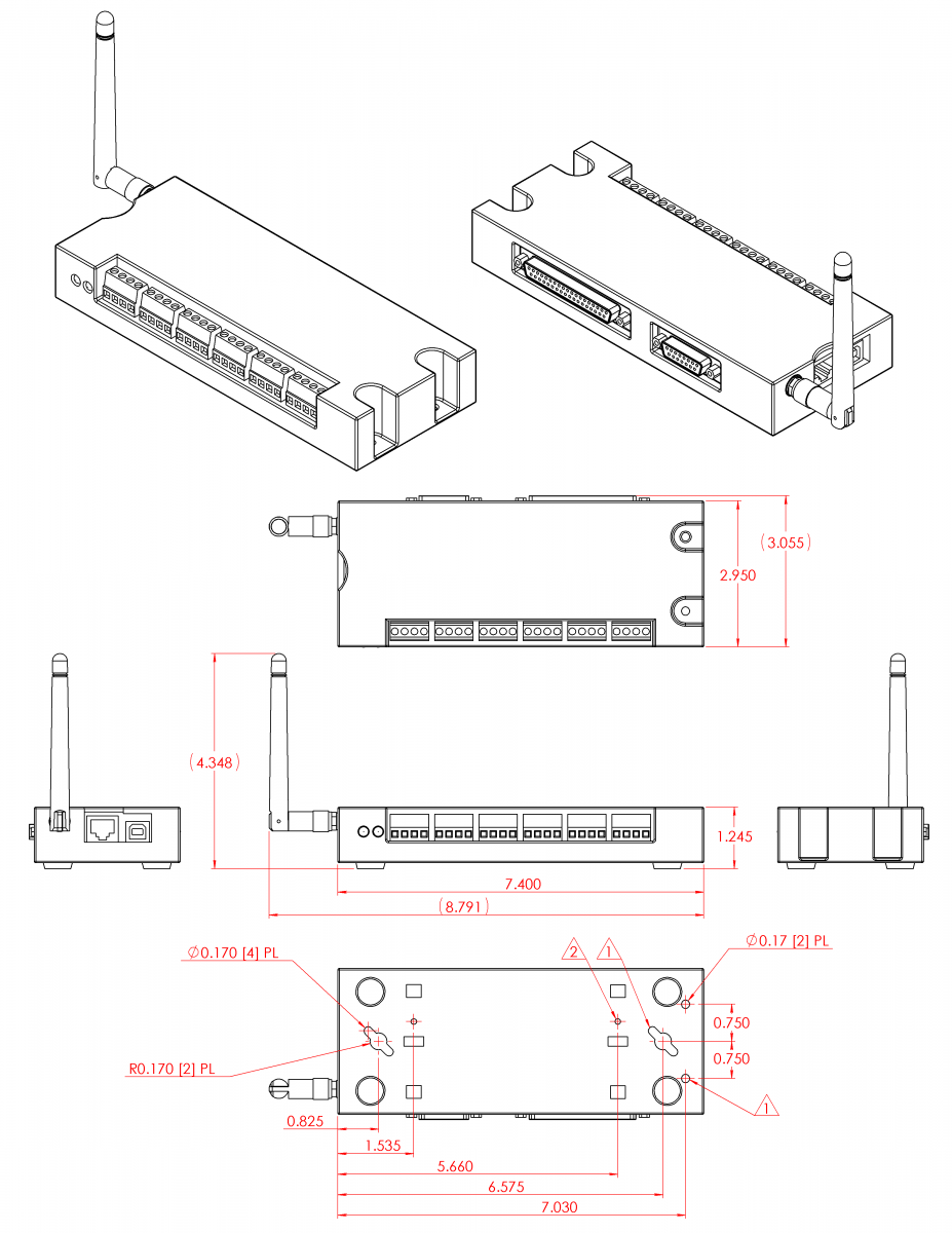
Mounting holes are sized for #8 panhead screws.
-
Receptacle holes for plastic DIN rail clip ( TKAD ).
-
The T7-Pro is depicted above. The standard T7 does not have a wireless antenna.
-
Dimensions in inches.
-
In addition to the above, there are 6 holes on the bottom of the enclosure with screws to hold the enclosure together; these are #4 panhead screws with 5/8in. length.
More Details
See the OEM page for details on connector pin-headers, holes, power supply information, part options, and more.
Common neutral format CAD models are provided below. Right-click and select the "Save link as..." option to download STEP files.