6.0 Ethernet [T-Series Datasheet]
Communication Protocol: Modbus TCP
Connector Type: RJ-45 Socket, Cat 5
Compatible: 10/100Base-T, Auto-MDIX
PoE (Power over Ethernet): T8 only. T4 or T7 See PoE App Note.
Max Cable Length: 100 meters typical
Max Packet Size: 1040 bytes/packet (TCP), 64 bytes/packet (UDP)

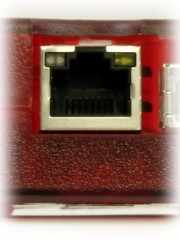
LabJack RJ-45/Ethernet Connector
The T-series devices each have a 10/100Base-T Ethernet connection. Depending on the device, this connection can be used for communication, power, or both.
T4, T7 - This connection only provides communication. Power must be provided through the USB connector. A PoE splitter can be used, see the PoE App-note for more information.
T8 - This connection can be used for communication or power or both. Supplying power over the Ethernet cable is called Power over Ethernet (PoE). See the PoE Section for more information.
Refer to out WiFi and Ethernet tutorial to get started with Ethernet communication.
Ports
T-series devices will respond to connections or packets on the following ports:
502 (TCP) - Responds to Modbus TCP packets received over this port.
702 (TCP) - Sends spontaneous data such as stream to devices connected to this port.
52362 (UDP) - Responds to Modbus UDP packets received over this port. Usually used to search for T-series devices on a network.
If you need a wireless connection instead of Ethernet, you can buy a wireless bridge. Connect the T-series device to the bridge and the bridge will connect to the wireless network. Find more information in the Convert Ethernet to WiFi App Note.
The following table describes how many simultaneous connections can be maintained per connection type.
Connection Type | Number of Simultaneous Connections |
|---|---|
TCP (port 502, Modbus TCP server) | 2 |
TCP (port 702, spontaneous data only) | 1 |
UDP (port 52362) | Unlimited* |
* UDP is connectionless and it does not claim any device connection resources.
"But I Don't Know How To Speak Ethernet?"
Don't worry, the LJM Library takes care of the Ethernet details. You just make our Open call to get a handle to a particular device (e.g. HandleA), and then make simple calls such as eReadName(HandleA, "AIN0") which returns the voltage from analog input 0. We have examples for many development environments and even some simple ready-to-run software.
Config (_DEFAULT) Registers
Use the following _DEFAULT registers to configure Ethernet:
These registers can also be read. Configure the Ethernet network configurations in Kipling software.
These _DEFAULT registers are non-volatile. Whatever value you write to a _DEFAULT register will be retained through a reboot or power-cycle. New values written to these _DEFAULT registers are not applied until power-up or until a 1 is written to ETHERNET_APPLY_SETTINGS.
Status Registers
Use the following read-only registers to read the status of Ethernet:
Config (_DEFAULT) vs. Status Registers
Example: If you write ETHERNET_IP_DEFAULT="192.168.1.207" (you would actually write/read the 32-bit numeric equivalent—not an IP string), then that value will be retained through reboots and is the default IP address. If DHCP is disabled, this will be the static IP of the device and what you get if you read ETHERNET_IP. If DHCP is enabled, then a read of ETHERNET_IP will return the IP set by the DHCP server.
Power
The following registers configure Ethernet power:
Some Examples
Read IP Example: To read the wired IP Address of a device, perform a Modbus read of address 49100. The value will be returned as an unsigned 32-bit number, such as 3232235691. Change this number to an IP address by converting each binary group to an octet, and adding decimal points as necessary. The result in this case would be "192.168.0.171".
Change IP Example: To change the Ethernet IP Address of a device, perform a Modbus write to address 49150. The value must be passed as an unsigned 32-bit number, such as 3232235691. Change this IP address "192.168.0.171" by converting each octet to a binary group, and sticking them together.
Default IP Address
The default is DHCP enabled. If your network does not have a DHCP server, there are a few options to talk to the device so you can change Ethernet settings:
Use USB.
Connect to a network with a router (DHCP server).
Use the SPC-to-AIN3 jumper to temporarily force a static IP.
Isolation
The Ethernet connection on any T-series device has 1500 volts of galvanic isolation. All power supplies shipped by LabJack Corporation with T-series devices have at least 500 volts of isolation.
Note that if you power the T-series device from a USB host/hub, ground from the host/hub is typically connected to upstream USB ground, which often finds its way back to AC mains ground and thus there would be no isolation.
LEDs on the Ethernet jack
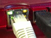
Both the green and orange LEDs on the Ethernet jack will illuminate on connection to an active Ethernet cable. The orange LED turns on when an active link is detected and blinks when packets are received/processed. The green LED illuminates when the connection is 100Mbps.

The orange LED is closest to the USB connector.
UDP Discovery-Only Mode - T7 only
Firmware minimum: 1.0284
It is theoretically possible that an unintended UDP packet could be received by a T-series device and processed. However, this is statistically unlikely. By one calculation, the statistical likelihood of this happening is less than 2.7E-10 percent.
However, if your application needs ultimate reliability or your network has Modbus UDP packets broadcast on port 52362, you can enable a discovery-only mode. Discovery-only mode disables all Modbus functionality except a small list of registers that LJM uses to identify devices. The error UDP_DISCOVERY_ONLY_MODE_IS_ENABLED (2317) indicates that an operation attempted to read/write a register outside of this list while discovery-only mode was enabled.
Use ETHERNET_UDP_DISCOVERY_ONLY to enable/disable discovery-only mode until the device is power-cycled:
Use the _DEFAULT register version to set the startup behavior for discovery-only mode:
There are separate WiFi-only configurations for discovery-only mode via WiFi.
