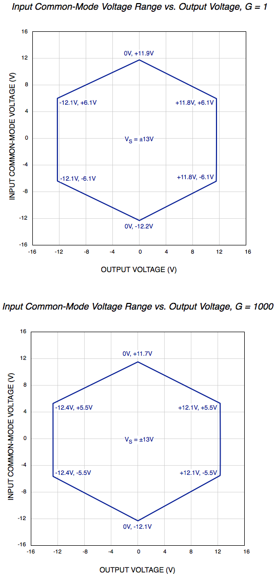
Following are figures showing the approximate signal range of the U6 analog inputs. "Input Common-Mode Voltage" or Vcm is (Vpos + Vneg)/2.
Keep in mind that the voltage of any input compared to GND should be within the Vm+ and Vm- rails by at least 1.5 volts, so if Vm is the typical ±13 volts, the signals should be within ±11.5 volts compared to GND.
Example #1: Say a differential signal is measured where Vpos is 10.05 volts compared to GND and Vneg is 9.95 volts compared to ground, and G=100. That means Vcm=10.0 volts, Vdiff=0.1 volts, and the expected Vout=10.0 volts. Figures for G=10 and G=100 are not available, but Vcm=10.0 volts and Vout=10.0 volts is not valid at G=1 or G=1000, so is certainly not valid for gains in between.
Example #2: Say a differential signal is measured where Vpos is 15.0 volts compared
to GND and Vneg is 14.0 volts compared to ground, and G=1. That means Vcm=14.5 volts, Vdiff=1.0 volts, and the expected Vout=1.0
volts. The voltage of each input compared to GND is too high, so this would not work at all.
Example #3: Say a single-ended signal is measured where Vpos is 10.0 volts compared
to GND and G=1. That means
Vcm=5.0 volts, Vdiff=10.0 volts, and the expected Vout=10.0
volts. This is fine according to the figure below.