2 - Hardware Description [U6 Datasheet]
Hardware Variants
The U6 is available in a few different variants.
U6- This is the normal version in a red enclosure.
U6-Pro - Same as the U6 with the addition of a 24-bit analog to digital converter.
U6-OEM - Does not include an enclosure. Most external connection components such as screw terminals are not included. This variant is intended for customers who want to connect to the LabJack device through ribbon cables or to custom PCB. Full details of the OEM version are available here: OEM Versions
U6-Pro-OEM - A U6-OEM with the pro additions. Full details of the OEM version are available here: OEM Versions
IO Summary
The U6 has 3 different I/O areas:
Communication Edge: Has a USB type B connector.
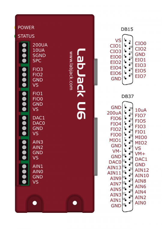
Screw Terminal Edge: Convenient connections for 4 analog inputs, both analog outputs, 4 flexible digital I/O (FIO), and both current sources. The screw terminals are arranged in blocks of 4, with each block consisting of Vs, GND, and two I/O. Also on this edge are two LEDs. One simply indicates power, while the other serves as a status indicator.
DB Edge: Has 2 D-sub type connectors: a DB37 and DB15. The DB37 has some digital I/O and all the analog I/O. The DB15 has 12 additional digital I/O (3 are duplicates of DB37 I/O).

Figure 2-1. Enclosure & Connectors
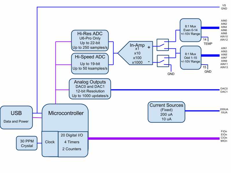
USB: All power and communication is handled by the USB interface.
LEDs: The Power and Status LEDs convey different information about the device.
GND/SGND: All GND terminals are the same. SGND has a self-resetting thermal fuse in series with GND.
VS: All VS terminals are the same. These are outputs that can be used to source about 5 volts.
10UA/200UA: Fixed current sources providing 10µA/200µA at a max voltage of about 3 volts.
AIN#: AIN0-AIN13 are the 14 analog inputs.
DAC#: DAC0 & DAC1 are the 2 analog outputs. Each DAC can be set to a voltage between about 0.02 and 5 volts with 12-bits of resolution.
FIO#/EIO#/CIO#/MIO#: These are the 20 digital I/O, and are also referred to as DIO0-DIO19. Besides basic digital I/O operations, some of these terminals can also be configured as Timers & Counters (frequency input, PWM output, etc.), SPI serial, I2C serial, and Asynchronous serial.
For information about reading inputs, start in Section 3. For information about setting outputs, start with the Waveform Generation Application Note.

Figure 2-2. Block Diagram
