The LabJack UE9 has 16 total built-in analog inputs. Two of these are connected internally (AIN14/AIN15), leaving 14 user accessible analog inputs (AIN0-AIN13). The first 4 analog inputs, AIN0-AIN3, appear both on the screw terminals and on the DB37 connector. These connections are electrically the same, and the user must exercise caution only to use one connection or the other, and not create a short circuit. Following is a table showing the channel number to pass to acquire different readings from the internal channels (AIN14/15).
Table 2.7.1-1. Internal Channels
|
Channel# |
|
|
14 |
Vref (~2.43 V) |
|
128 |
Vref (~2.43 V) |
|
132 |
Vsupply |
|
133 |
Temp Sensor |
|
15 |
GND |
|
136 |
GND |
|
140 |
Vsupply |
|
141 |
Temp Sensor |
GND and Vref connect 0.0 volts and about 2.43 volts to the internal channels. These signals come through the same input path as channels 0-13, and thus can be used to test various things. Vsupply connects the 5 volt supply voltage (Vs) directly to the analog to digital converter through a voltage divider that attenuates it by 40%. The attenuation of this voltage divider is not measured during the UE9 factory calibration, but the accuracy should typically be within 0.2%. Note that a reading from this channel returns Vs during the execution of the command, and Vs might dip slightly while increasing a command due to the increased current draw of the UE9, thus this reading might be slightly lower than a comparative reading from an external DMM which averages over a longer time. The channels with the same names are identical. For instance, channel 133 or 141 both read the same internal temperature sensor. See "Section 2.7.4":/support/ue9/users-guide/2.7.4 for information about the internal temperature sensor. The "Mux80":/catalog/mux80 accessory uses multiplexer ICs to easily expand the total number of analog inputs available from 14 to 84, or you can connect multiplexer chips yourself. The DB37 connector has 3 MIO lines designed to address expansion multiplexer ICs (integrated circuits), allowing for up to 112 total external analog inputs. The MAX4051A (maxim-ic.com) is a recommended multiplexer, and a convenient ±5.8 volt power supply is available so the multiplexers can pass bipolar signals (see Vm+/Vm- discussion in "Section 2.12":/support/ue9/users-guide/2.7.4).
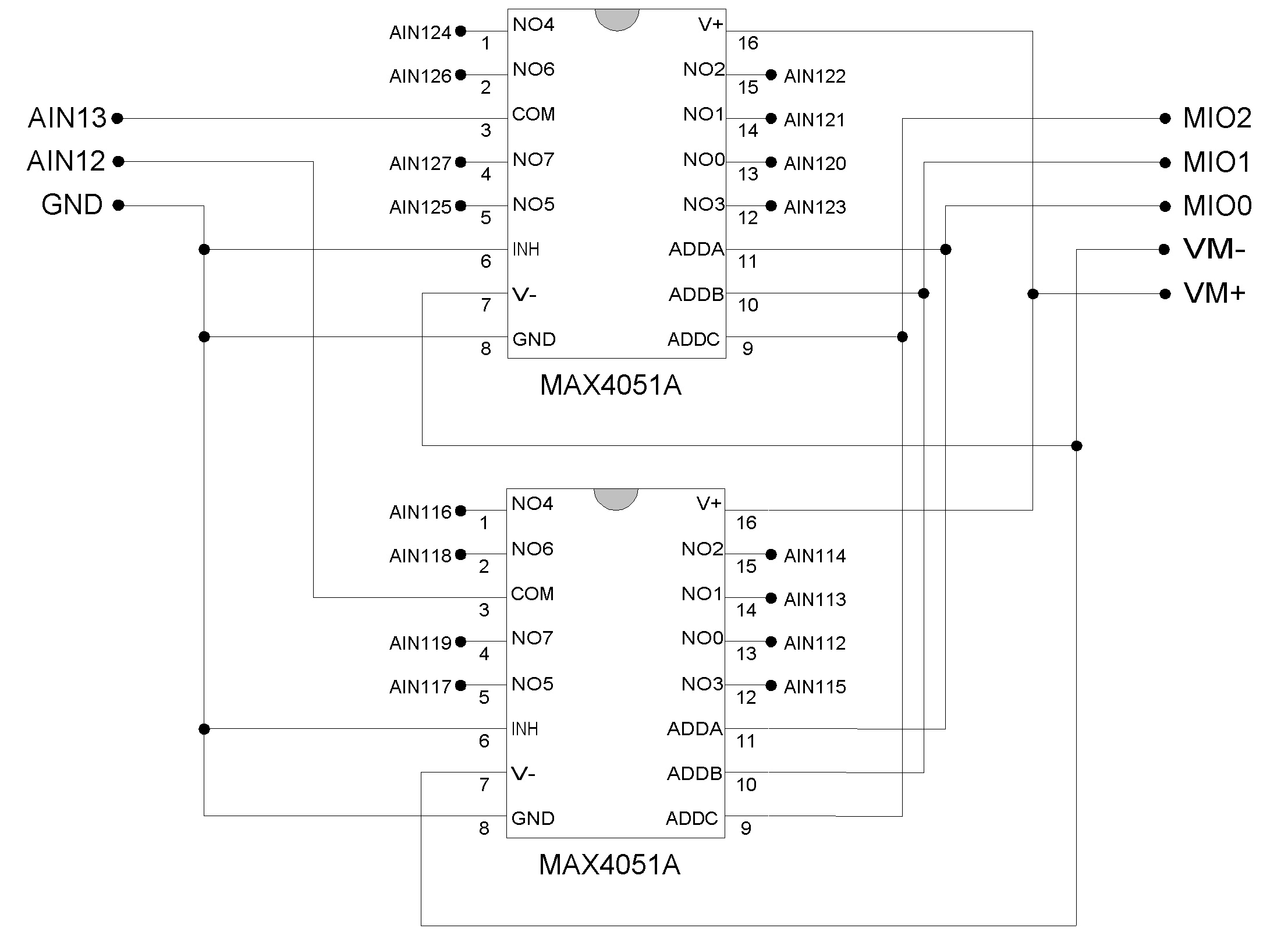
To make use of external multiplexers, the user must be comfortable reading a simple schematic (such as Figure 2-2) and making basic connections on a solderless breadboard. Initially, it is recommended to test the basic operation of the multiplexers without the MIO lines connected. Simply connect different voltages to NO0 and NO1, connect ADDA/ADDB/ADDC to GND, and the NO0 voltage should appear on COM. Then connect ADDA to VS and the NO1 voltage should appear on COM. If any of the AIN channel numbers passed to a UE9 function are in the range 16-127 (extended channels), the MIO lines will automatically be set to output and the correct state while sampling that channel. For instance, a channel number of 28 will cause the MIO to be set to b100 and the ADC will sample AIN1. Channel number besides 16-127 will have no affect on the MIO. The extended channel number mapping is shown in Table 2-2. For differential extended channels, the positive channel must map to an even channel from 0-12, and the negative channel must map to the odd channel 1 higher (i.e. 1-13). That means that for extended channel numbers the negative channel must be 8 higher than the positive channel. For example, a valid differential extended channel pair would be Ch+ = AIN70 and Ch- = AIN78, since AIN70 maps to AIN6 and AIN78 maps to AIN7. For more information on differential extended channels, see the "Mux80 Datasheet":/support/mux80/datasheet. In command/response mode, after sampling an extended channel the MIO lines remain in that same condition until commanded differently by another extended channel or another function. When streaming with any extended channels, the MIO lines are all set to output-low for any non extended analog channels. For special channels (digital/timers/counters), the MIO are driven to unspecified states. Note that the StopStream can occur during any sample within a scan, so the MIO lines will wind up configured for any of the extended channels in the scan. If a stream does not have any extended channels, the MIO lines are not affected.
Table 2.7.1-3. Expanded Channel Mapping
|
UE9 |
MIO Multiplexed |
|
Channel |
Channels |
|
0 |
16-23 |
|
1 |
24-31 |
|
2 |
32-39 |
|
3 |
40-47 |
|
4 |
48-55 |
|
5 |
56-63 |
|
6 |
64-71 |
|
7 |
72-79 |
|
8 |
80-87 |
|
9 |
88-95 |
|
10 |
96-103 |
|
11 |
104-111 |
|
12 |
112-119 |
|
13 |
120-127 |
|
14 |
128-135 |
|
15 |
136-143 |