T7 AIN Signal Range
This section is only needed for differential measurements where neither channel (positive or negative) is at 0 volts. For single-ended measurements see the simple ranges at the beginning of Table A.3-2.
The instrumentation amplifier in the T7 (see Figure 4.2-2) provides 4 different gains:
-
x1 (RANGE is ±10 volts)
-
x10 (RANGE is ±1 volts)
-
x100 (RANGE is ±0.1 volts)
-
x1000 (RANGE is ±0.01 volts)
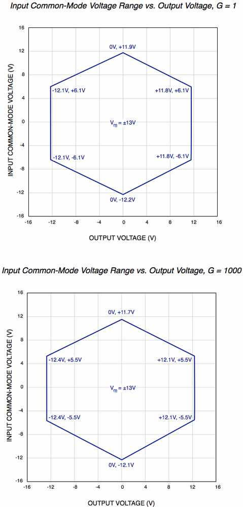
The figures below show the approximate signal range of the T7 analog inputs at gains of x1 and x1000.
Input Common-Mode Voltage, known as Vcm, is:
Vcm = (Vpos + Vneg)/2
The voltage of any input compared to GND should be within the VM+ and VM- rails by at least 1.5 volts, so if VM+ and VM- is the typical ±13 volts, the signals should be within ±11.5 volts compared to GND. See Table A5-8 for more information on VM+ and VM-.
Example #1 - invalid because Vcm=10.0 with Vout=10.0 is invalid:
Suppose a differential signal is measured, where:
-
Vpos is 10.05 volts compared to GND
-
Vneg is 9.95 volts compared to GND
-
G=100 (RANGE=±0.1)
That means:
-
Vcm=10.0 volts,
-
Vdiff=0.1 volts,
-
and the expected Vout=10.0 volts.
Figures for G=10 and G=100 are not shown, but Vcm=10.0 volts and Vout=10.0 volts is not valid at G=1 or G=1000, so it is not valid for gains in between.
Example #2 - invalid because Vpos compared to GND is too high:
Suppose a differential signal is measured, where:
-
Vpos is 12.0 volts compared to GND
-
Vneg is 8.0 volts compared to GND
-
G=1 (RANGE=±10)
That means:
-
Vcm=10.0 volts,
-
Vdiff=4.0 volts,
-
and the expected Vout=4.0 volts.
This looks almost okay in the G=1 figure below, but the voltage of Vpos compared to GND is too high so this is not valid.
Example #3 - valid:
Suppose a single-ended signal is measured, where:
-
Vpos is 10.0 volts compared to GND
-
G=1 (RANGE=±10)
That means:
-
Vcm=5.0 volts,
-
Vdiff=10.0 volts,
-
and the expected Vout=10.0 volts.
This is fine according to the figure below.

