A strain gauge (or gage) is a resistive element whose resistance changes with strain. The change in resistance is small, so a bridge circuit is commonly used for measurement. Look for signal-conditioning hardware that includes bridge completion, or complete the bridge yourself.
Strain Gauge Fundamentals
Relating Strain to a Change in Resistance
Strain to a wire (or similar media) reflects a change in wire length. Deformation from forces applied to a wire can also change the cross-sectional area of the wire. This will cause a change in resistance per Pouillet's law (R = ρL/A) hence providing a relationship between resistance and mechanical strain.
Practical Specifications
In practice, you should receive information about the Gauge Factor (GF) with your strain gauge. Sometimes gauge factor is also specified as sensitivity. This provides a direct relationship between strain and change in resistance:
ε = (ΔR/R0) / GF
Where ε is the strain, R0 is the nominal resistance of the strain, ΔR is the change in resistance, and GF is the gauge factor. It is important to note that tension in a strain gauge will result in an increase in the strain gauge resistance, whereas compression to the strain gauge will result in a decrease in strain resistance.
A common nominal strain gauge resistance is 350 Ω and a common gauge factor is roughly 2.
If your strain gauges are configured in a full bridge circuit, your datasheet may only have information about sensitivity and a rated load, which can be even easier than working directly with strain gauges. In that case, see our Bridge Circuit App Note for further setup and measurement information.
General Equations
Strain measurements should typically be configured in a bridge circuit to aid in measuring the small resistance changes. A typical bridge circuit diagram is provided below.
If your LabJack analog inputs are isolated like the T8, then you do not need to connect Vexc- to LabJack GND.
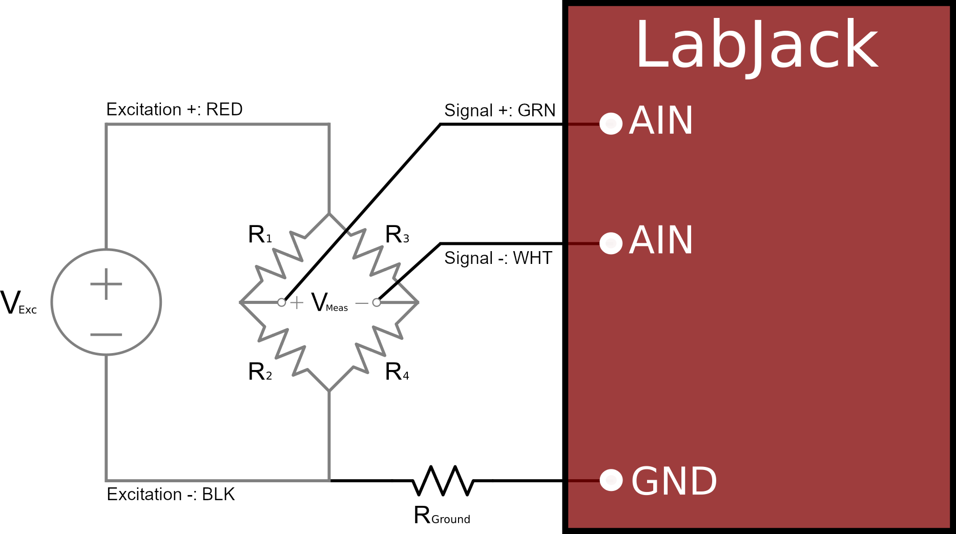
Start by finding the nodal voltages that will result in Vmeas using the resistor divider equations:
Vmeas+ = Vexc * R2 / (R1 + R2)
Vmeas- = Vexc * R4 / (R3 + R4)
Vmeas is simply the difference between these two nodal voltages:
Vmeas = Vmeas+ - Vmeas-
Vmeas = [Vexc * R2 / (R1 + R2)] - [Vexc * R4 / (R3 + R4)]
One or multiple strain gauges can replace each of the resistor positions in a bridge circuit. One important expression of the strain gauge resistance is as follows:
ΔR = Rstrain- R0
Where ΔR is the change in resistance, Rstrain is the measured strain gauge resistance, and R0 is the nominal strain gauge resistance. Rearranging to get the expression in terms of Rstrain:
Rstrain= ΔR + R0
Quarter-bridge Calculations
Swapping in the formula we found for Rstrain into the bridge equation in place of R2 (quarter bridge circuit):
Vmeas = [Vexc * (ΔR + R0 ) / (R1 + ΔR + R0)] - [Vexc * R4 / (R3 + R4)]
Since each resistor should be selected to have equal resistance, this equation can be simplified as follows:
Vmeas = [Vexc* (ΔR + R) / (R + ΔR + R)] - [Vexc * R / (R + R)]
Vmeas = [Vexc* (ΔR + R) / (2R + ΔR)] - (Vexc/2)
Vmeas /Vexc= [(ΔR + R) / (2R + ΔR)] - (1 / 2)
Vmeas /Vexc= [(2ΔR + 2R) / (4R + 2ΔR)] - (2R + ΔR / 4R + 2ΔR)
Vmeas /Vexc= ΔR / (4R + 2ΔR)
Vmeas= ΔR*Vexc/ (4R + 2ΔR)
If we swap in ΔR in terms of strain ε and gauge factor GF:
ΔR = ε * GF * R
Vmeas= (ε * GF * R)*Vexc / [4R + 2(ε * GF * R)]
Vmeas= Vexc / [4R/(ε * GF * R) + 2]
4Vmeas/(ε * GF) + 2Vmeas = Vexc
4Vmeas/ (Vexc-2Vmeas)=ε * GF
ε = 4Vmeas/ [GF(Vexc-2Vmeas)]
Strain Gauge Bridge Completion
Unfortunately, we do not currently have any accessories designed for bridge completion. We would recommend looking for strain gauges already configured as full-bridge circuits if possible, as this would avoid the need to do bridge completion.
If you must work with individual strain gauges, some options might be to use a breadboard, solder together the circuit using our LJTick-Proto, or find a 3rd party bridge completion module like the following module from Campbell Scientific.
Excitation
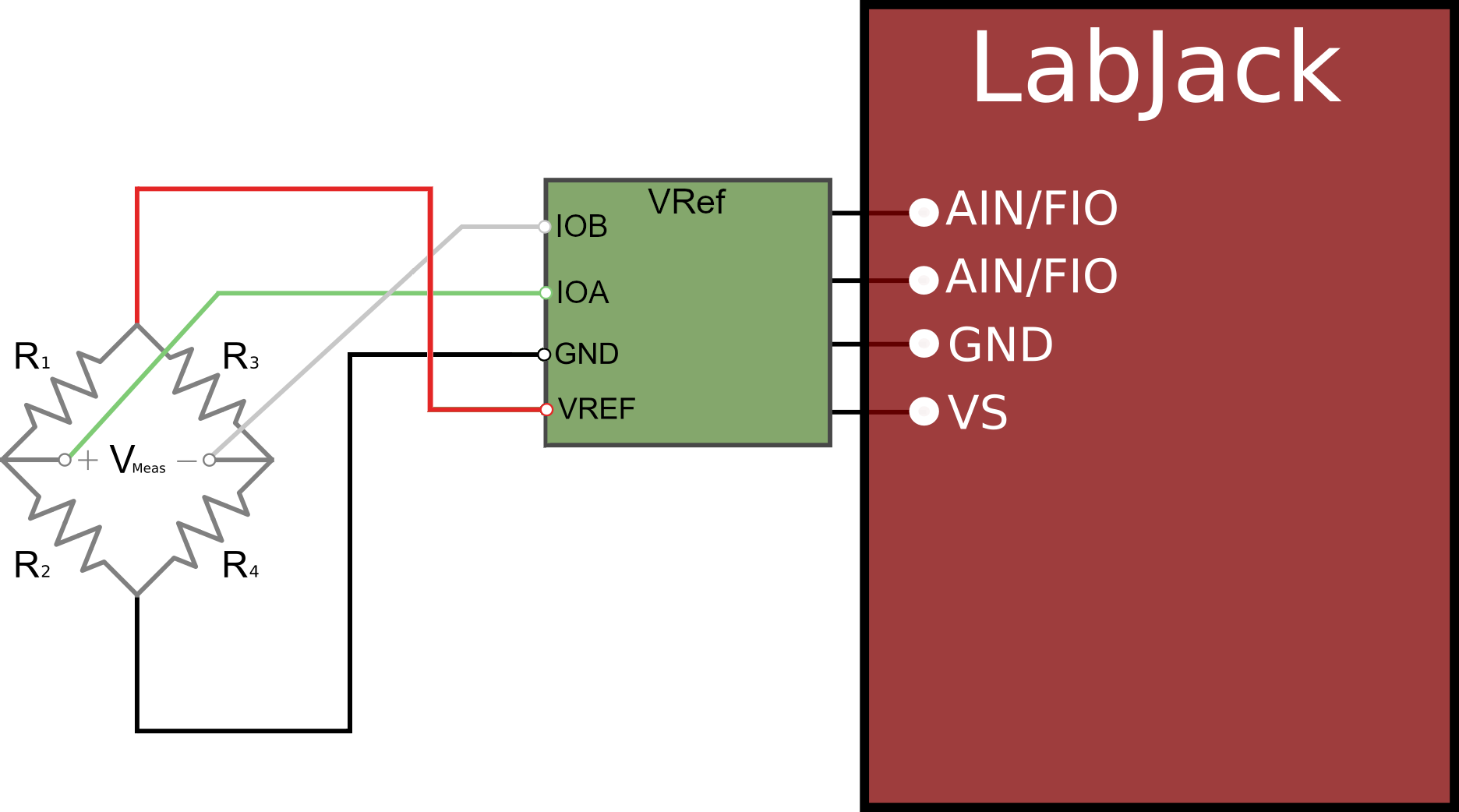
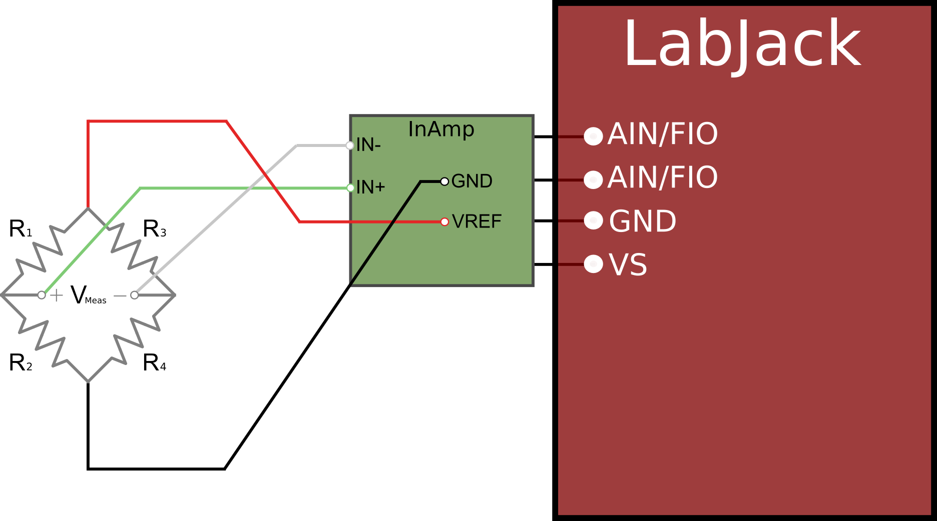
We recommend using our LJTick-Vref-41 for excitation, or if you are using the LJTick-InAmp, use the provided VREF terminal - see figures below for connection details. After going through the remaining sections below, see our Bridge Circuit App Note for further setup and measurement information.
Dummy Resistors for Wheatstone Bridge Completion
Resistors with similar values to the nominal strain gauge resistance can be used to complete a Wheatstone bridge circuit. The biggest downside to this method is that it does not compensate well for temperature effects on the strain measurement, and these can show up as errors in the measurement.
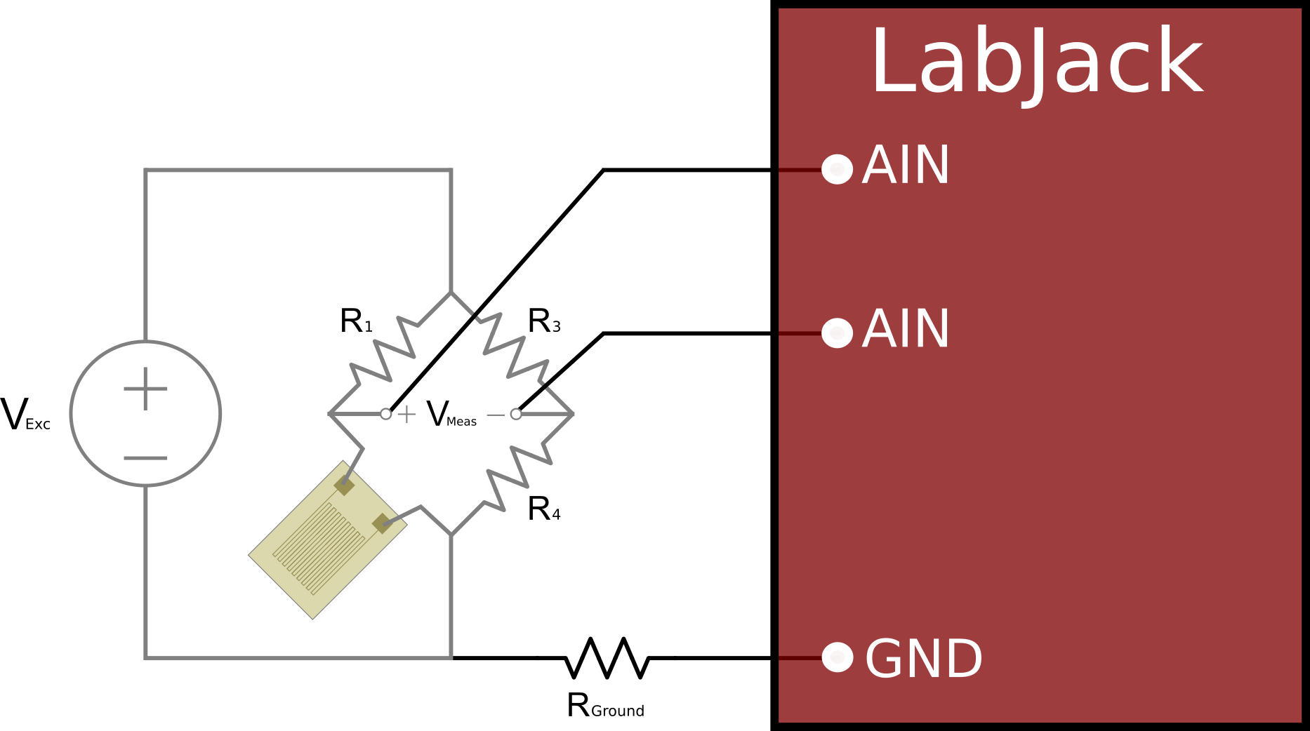
This would be considered a quarter-bridge configuration since there is only 1 out of 4 active strain gauges. The quarter-bridge calculations provided above can be used to find strain, assuming the dummy resistors are sized to have equal resistance to the strain gauge nominal resistance, and if you neglect temperature effects:
ε = 4Vmeas/ [GF(Vexc-2Vmeas)]
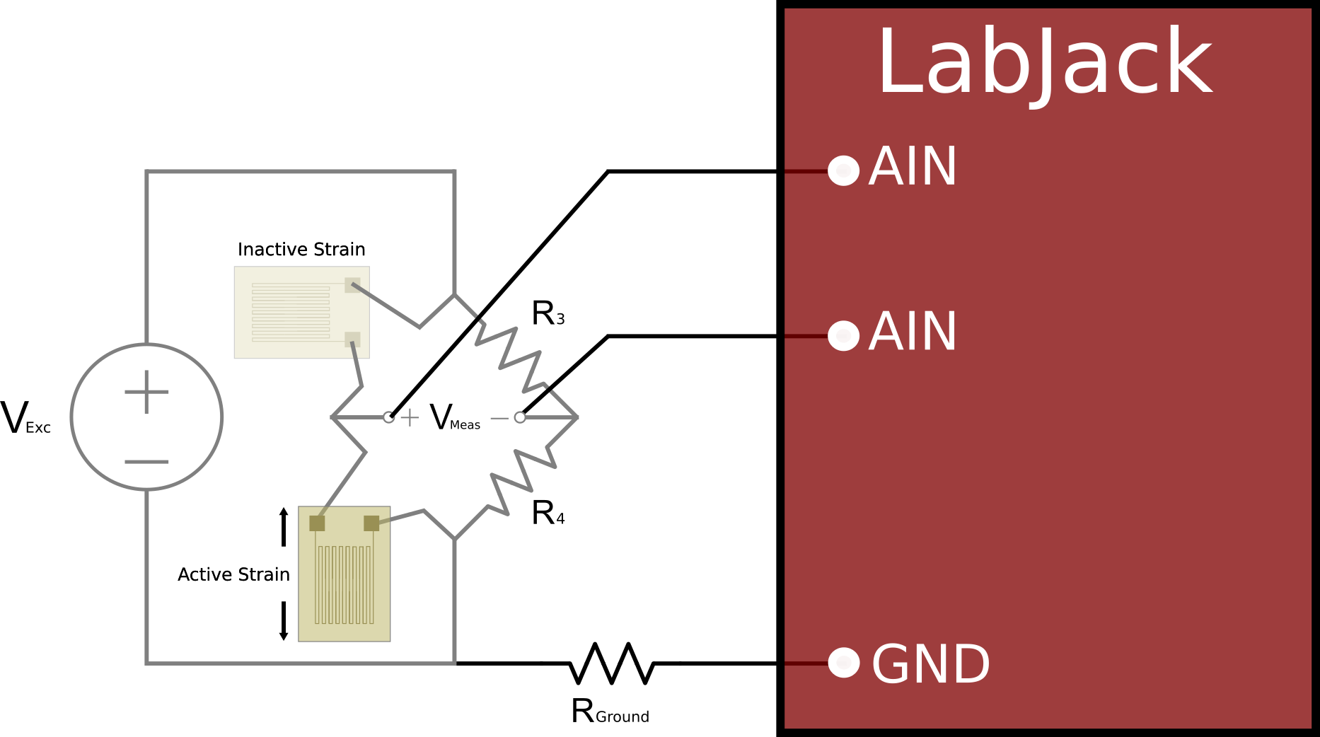
Inactive Strain Gauges for Wheatstone Bridge Completion
An improvement from using dummy resistors for bridge completion is to instead use a second identical strain gauge, oriented such that it will not see any strain during the test/measurement.
The two strain gauges should be placed opposite of each other on the same leg of the Wheatstone bridge. Since both of the strain gauge elements are of the same material, the resistance change of each element due to temperature will be equal and offset each other in the bridge circuit measurement. This would be considered a quarter-bridge configuration since only 1 out of 4 bridge elements is an active strain gauge.
The quarter-bridge calculations above can be used to find strain, assuming any dummy resistors are sized to have equal resistance to the strain gauge nominal resistance:
ε = 4Vmeas/ [GF(Vexc-2Vmeas)]
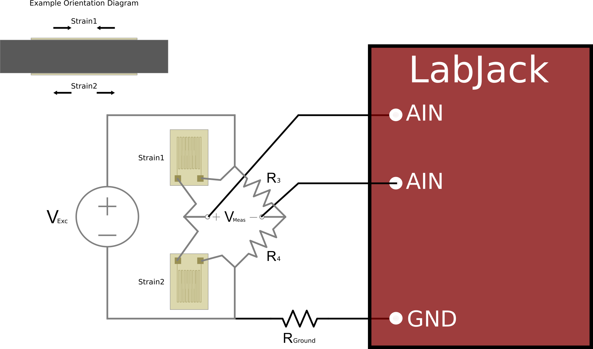
Active Strain Gauges to Create a Half-bridge Circuit
One common strain measurement configuration is to place two strain gauges on the same leg of the Wheatstone bridge and orienting them so that they see the strain of interest in opposite directions (one oriented so that it will experience compression and the other tension). This will effectively double the output sensitivity and also compensate well for temperature effects. This would be a half-bridge configuration since there are two active strain gauges.
From the general bridge circuit equations:
Vmeas = [Vexc* (ΔR2 + R02) / (ΔR1 + R01 + ΔR2 + R02)] - [Vexc * R4 / (R3 + R4)]
With the setup above, ΔR2 = -ΔR1 and each nominal resistance should also be equal:
Vmeas = [Vexc* (ΔR + R) / (ΔR + R - ΔR + R)] - [Vexc * R / (R + R)]
Vmeas = [Vexc* (ΔR + R) / (R + R)] - [Vexc * R / (R + R)]
Vmeas = Vexc( ΔR + R -R)/ (R + R)
Vmeas = Vexc(ΔR)/ 2R
Right away we can see that this half bridge has roughly twice the output voltage change per unit strain compared to a quarter bridge. If we swap in ΔR in terms of strain ε and gauge factor GF:
ΔR = ε * GF * R
Vmeas = Vexc(ε * GF * R)/ 2R
Vmeas = Vexc*ε * GF / 2
ε = 2Vmeas / (GF * Vexc)
Active Strain Gauges to Create a Full-bridge Circuit
The half-bridge setup can be expanded to use 4 active strain gauges.
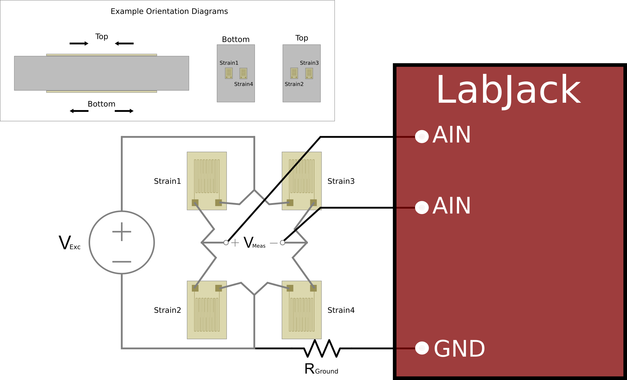
We can follow the relationships found with quarter-bridge and half-bridge circuits and see that a full-bridge circuit should output ~4x the output change per unit strain when compared to a quarter bridge:
Vmeas = Vexc(ΔR)/ R
ε = Vmeas / (GF * Vexc)
Other Configurations
The information above can be used to find relationships with more novel strain gauge configurations.
For example, consider a full bridge circuit where one leg of the bridge using strain gauges oriented 90 degrees from the other leg as shown in Figure 6 below.
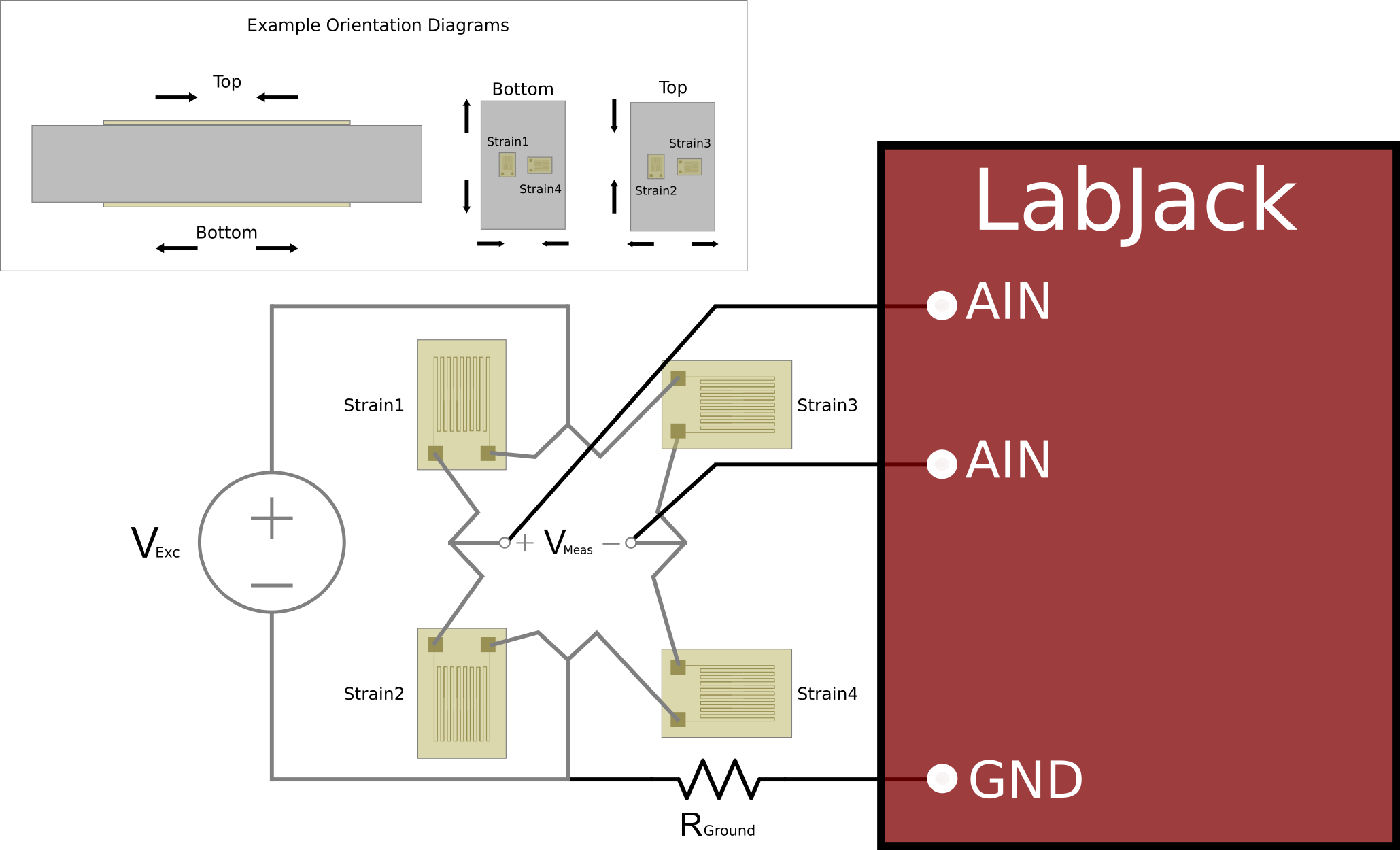
If you only apply a force that causes strain in one direction, one leg of the bridge would look like inactive strain gauges, and the half-bridge equations would apply:
Vmeas = Vexc*εdirection1* GF / 2
It follows that the output voltage would change according to the summation of strain that our strain gauges are oriented to measure:
Vmeas = Vexc* (εdirection1+ εdirection2)* GF / 2
Note: If the readings from the bridge circuit are the opposite of what you expect, try reversing the bridge signal output wires to the LabJack.