Overview
The Extended Channels feature dramatically expands a LabJack DAQ device's analog input capacity by controlling external multiplexers. Each multiplexer routes one of its, up to eight, external analog signals into a single LabJack analog input, effectively multiplying the total available channels by as much as eight times.
Sampling Rate Limitations
When using Extended Channels, the normal sampling rate limitation apply. For instance, a T7 can sample 10 channels at 10 kHz each, or 50 Channels at 2 kHz each.
Prerequisites
Before using this feature, make sure you're familiar with how T-Series devices operate. The Quickstart Guides are a great resource to get started.
Hardware
The Extended Channels feature requires both a compatible DAQ and a multiplexing system. Currently, as of July 2025, the following devices support Extended Channels:
-
T7: The T7 has 14 built-in analog inputs (AIN0 through AIN13). Up to 112 total external analog inputs can be utilized by multiplexing the built-in analog inputs. By multiplexing these inputs, The T7 can measure up to 112 analog signals.
-
Mux80: The Mux80 accessory expands the T7's AIN4-AIN13, increasing them from 10 inputs to 80. AIN0 through AIN3 remain available on the screw terminals of the T7, for a total of 84 analog signal connections. For further details, see the Mux80 Datasheet.
Software
-
Firmware: Be sure to use the Latest T7 firmware when using the Extended Channels feature.
-
Driver: All versions of the LJM driver support Extended Channels.
-
Kipling: Kipling supports extended channels through the Register Matrix and through Lua Scripting.
-
Custom Applications: Custom applications will only need to change the channel numbers.
-
LJLogM and LJStreamM: Older versions of these programs could only collect data from 16 channels. The newer versions have been expsnded
Operation
The Extended Channels feature utilizes multiplexers to connect one of eight analog signals to a single analog input on the T-Series device. The selection of the active channel is controlled by the states of the MIO lines.
Multiplexing
Multiplexing allows a single analog input to access multiple signals. For example, an 8-to-1 multiplexer enables eight separate signals to share one analog input. When a built-in channel is multiplexed, the original channel is replaced by the new expanded range. For instance, if AIN4 is multiplexed, it is no longer available as a single input because the multiplexer is selecting one of channels, AIN48 through AIN55, to be fed into AIN4.
Channel Mapping
Both built-in and extended channels are selected using a single channel map. The ranges define their purpose:
-
0-15: These represent the analog inputs on the T7.
-
16-127: These are extended channels.
Channel Decoding
Normally, LabJack hardware automatically handles the decoding of extended channel numbers. We provide these details here to assist with troubleshooting and custom application development.
An Extended Channel number can be converted into its corresponding MIO states and analog input channel number (AIN#) using the following formulas:
MIO State: The MIO State is derived from the lower three bits of the channel number:
-
MIO = Channel# % 8(where%is the modulus operator) -
Alternatively:
MIO = Channel# & 0x07(where&is a bitwise AND between an integer and hexadecimal7)
Analog Input Channel (AIN#):
-
For Extended Channels (Channel# ≥ 16):
-
AIN# = (Channel# - 16) / 8(integer division) -
Alternatively:
AIN# = (Channel# - 16) >> 3(where>>is a binary right shift operator)
-
-
For Built-in Channels (Channel# < 16):
-
AIN# = Channel#
-
The below table show the MIO state and the built-in AIN# for each extended channel #.
|
Output State |
Expanded Channel Multiplexing Mapping |
|||||||||||||||
|---|---|---|---|---|---|---|---|---|---|---|---|---|---|---|---|---|
|
MIO0 |
MIO1 |
MIO2 |
AIN0 |
AIN1 |
AIN2 |
AIN3 |
AIN4 |
AIN5 |
AIN6 |
AIN7 |
AIN8 |
AIN9 |
AIN10 |
AIN11 |
AIN 12 |
AIN 13 |
|
0 |
0 |
0 |
16 |
24 |
32 |
40 |
48 |
56 |
64 |
72 |
80 |
88 |
96 |
104 |
112 |
120 |
|
1 |
0 |
0 |
17 |
25 |
33 |
41 |
49 |
57 |
65 |
73 |
81 |
89 |
97 |
105 |
113 |
121 |
|
0 |
1 |
0 |
18 |
26 |
34 |
42 |
50 |
58 |
66 |
74 |
82 |
90 |
98 |
106 |
114 |
122 |
|
1 |
1 |
0 |
19 |
27 |
35 |
43 |
51 |
59 |
67 |
75 |
83 |
91 |
99 |
107 |
115 |
123 |
|
0 |
0 |
1 |
20 |
28 |
36 |
44 |
52 |
60 |
68 |
76 |
84 |
92 |
100 |
108 |
116 |
124 |
|
1 |
0 |
1 |
21 |
29 |
37 |
45 |
53 |
61 |
69 |
77 |
85 |
93 |
101 |
109 |
117 |
125 |
|
0 |
1 |
1 |
22 |
30 |
38 |
46 |
54 |
62 |
70 |
78 |
86 |
94 |
102 |
110 |
118 |
126 |
|
1 |
1 |
1 |
23 |
31 |
39 |
47 |
55 |
63 |
71 |
79 |
87 |
95 |
103 |
111 |
119 |
127 |
MIO
The MIO lines control the multiplexer channel selection (refer to Channel Decoding above). When Extended Channels are not in use, these MIO lines can function as normal digital I/O. The first time an extended analog input channel (AIN16 or above) is read, the MIO lines will automatically configure as outputs and their states will be controlled by the requested channel. Subsequent analog input readings will continue to set the MIO line states until the device is restarted.
Differential Channel Pairings
When using channel numbers greater than 16 (i.e., extended channels), differential pairs are spaced 8 channels apart. This is due to the T-series device's architecture where even-numbered built-in AINs inherently serve as the positive input for a differential pair, and the adjacent odd-numbered built-in AINs are the corresponding negative input.
Each multiplexer selects one of eight channels to connect to a single built-in AIN. For example:
-
AIN48-55 are connected to AIN4. Since AIN4 is an even-numbered input, it must always be the positive input of a differential signal.
-
AIN56-63 are connected to AIN5. Since AIN5 is an odd-numbered input, it must always be the negative input of a differential signal.
All multiplexers are controlled by a single set of addressing lines, meaning they simultaneously select the same input index. For example, if the MIO lines select input index 1, the multiplexer connected to AIN4 will select AIN49, and the multiplexer connected to AIN5 will select AIN57. The table in the Channel Decoding section further illustrates this concept.
Configuring Extended Channels
Extended channels support all the same settings as built-in analog inputs and are configured identically. The _ALL registers apply to both extended and built-in channels. The table below lists the configuration control registers and displays the adjusted channel numbers. Please note that AIN_EF also supports extended channels, but its specific registers are not included in this table.
Custom Multiplexing Applications
Custom multiplexing and signal conditioning boards can be designed and automatically controlled by a T7 using the DG408 multiplexing IC from Intersil. The DG408 multiplexing IC from Intersil is the recommended multiplexer, and a convenient ±12 volt power supply is available on the DB37 so the multiplexers can pass bipolar signals (see Vm+/Vm- documentation in Section 16.0). These are the same ICs that do the device's internal channel multiplexing as well as the ICs integrated into the Mux80. Figure 14.2.1 shows the typical connections for a pair of multiplexers.
Figure 14.2.1 Typical DG408DVZ Multiplexer Connections.
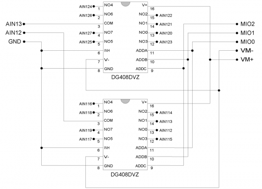
More information about adding your own multiplexers can be found in Section 2.6.1 of the U6 Datasheet.