The Mux80 AIN Expansion Board serves to provide an additional 80 analog inputs to any compatible LabJack. It uses 10 multiplexer chips connected to AIN4-AIN13 and splits each channel into 8 additional channels. When a specific extended analog input channel is read on a U6, UE9, or T7, the digital output MIO lines are automatically set and the correct analog channel is read. The Mux80 has a built-in DC-DC converter which provides the upper and lower rail voltages necessary for powering the multiplexer chips.
The Mux80 connector X2 provides access to 12 analog input channels. Note that 4 of these channels are alternate connections for AIN0-3. Connectors X3, X4, and X5 each provide access to 24 analog input channels.
For screw-terminal access, connect one or multiple CB37 Terminal Boards. Reference Table 1 below or the chart printed at the top of the Mux80 for wiring guidance.
Subsections
Features
-
80 Multiplexed Channels (or 40 Differential Pairs)
-
Built-In DC-DC Converter
-
OEM Capability
-
Easy-To-Use High Density Connectors
-
LJ-Snap2D/DIN-rail compatible, with TE Connectivity P/N TKAD
OEM Version
The MUX80-OEM is a "bare-board" version of the MUX80, providing maximum integration flexibility by allowing customers to install connectors of their choosing. The differences between the MUX80 and the MUX80-OEM are:
-
Installed Parts: The board comes populated with the essential multiplexing integrated circuits (ICs) and the core circuitry. It does not include D-sub connectors or the plastic carrier.
-
Soldering and Integration This is not a "plug-and-play" device. To make the MUX80-OEM functional, users must solder their own connectors, pin headers, or wires directly to the PCB. The board has mounting locations for D-sub connectors (X) or 0.1” pitch 2x20 pin headers (J):
-
Host Connection (to T7/U6): Use location X1 or J1.
-
Signal Connectors: Use locations X2/J2 through X5/J5.
See appendix A for connector locations and pinouts.
-
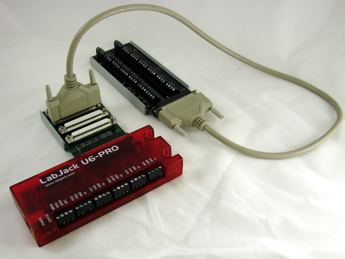
Connection Options
The Mux80 can be connected several ways. The images below demonstrate use with the CB37 Terminal Board, and several 3ft DB37 Cables.
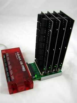
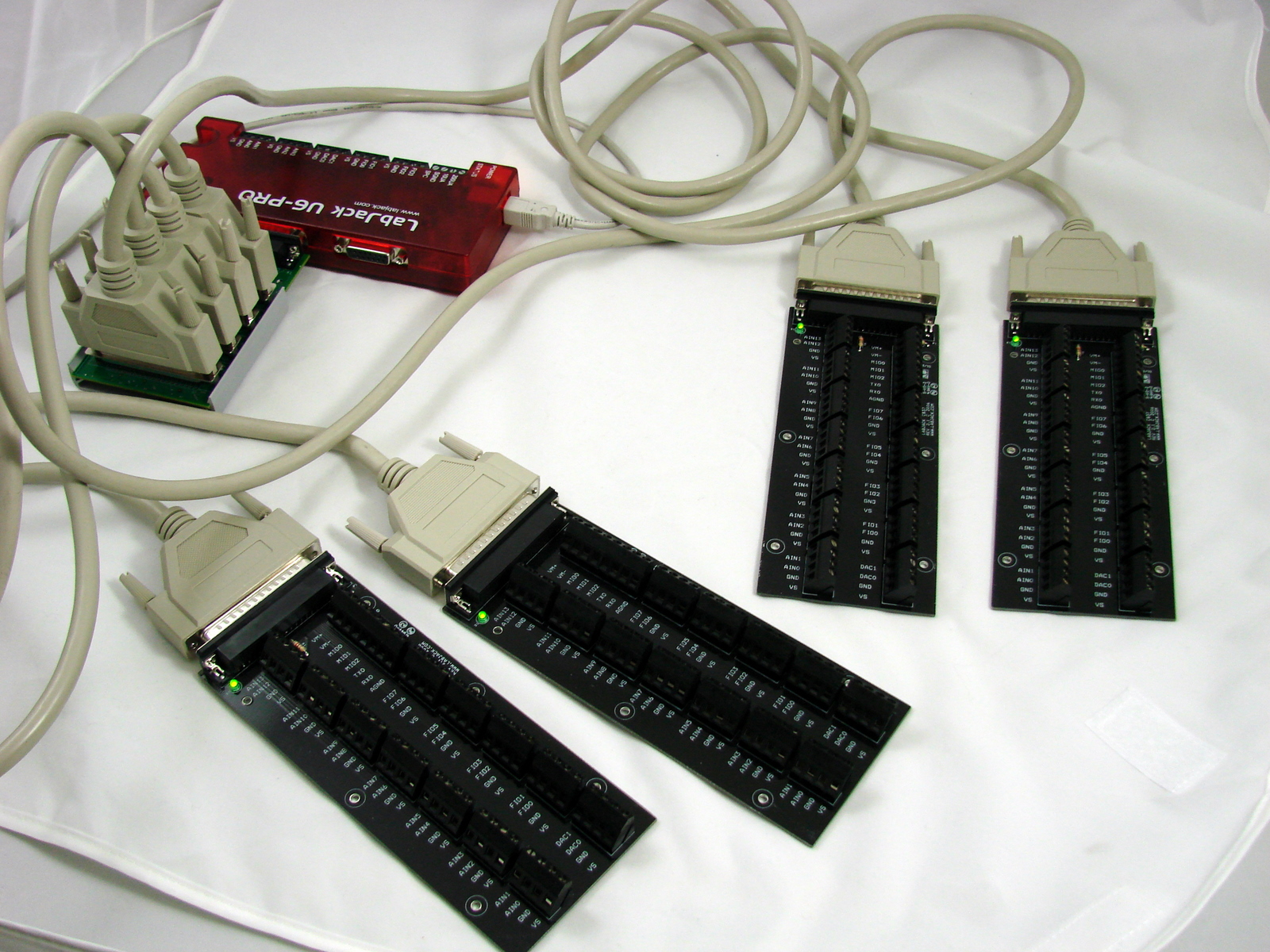
Table 1 describes how CB37 terminal labels translate to Mux80 connections. Note that Mux80 analog inputs sometimes appear on CB37 terminals that are not labeled as AIN. For example, AIN71 appears on the CB37 terminal labeled FIO7 when connected to Mux80 X3.
If you are not using CB37 boards with the MUX80, see Appendix A or the CB37 Datasheet to translate the CB37 terminals to DB37 pin numbers.
Table 1. CB37 to MUX80 connection chart
|
CB37 |
X2 |
X3 |
X4 |
X5 |
|---|---|---|---|---|
|
AIN13 |
N/C |
AIN61 |
AIN85 (93-) |
AIN109 |
|
AIN12 |
N/C |
AIN60 |
AIN84 (92-) |
AIN108 |
|
AIN11 |
AIN127 |
AIN59 |
AIN83 (91-) |
AIN107 |
|
AIN10 |
AIN126 |
AIN58 |
AIN82 (90-) |
AIN106 |
|
AIN9 |
AIN125 |
AIN57 |
AIN81 (89-) |
AIN105 |
|
AIN8 |
AIN124 |
AIN56 |
AIN80 (88-) |
AIN104 |
|
AIN7 |
AIN123 |
AIN55 (63-) |
AIN79 |
AIN103 (111-) |
|
AIN6 |
AIN122 |
AIN54 (62-) |
AIN78 |
AIN102 (110-) |
|
AIN5 |
AIN121 |
AIN53 (61-) |
AIN77 |
AIN101 (109-) |
|
AIN4 |
AIN120 |
AIN52 (60-) |
AIN76 |
AIN100 (108-) |
|
AIN3 |
AIN3 |
AIN51 (59-) |
AIN75 |
AIN99 (107-) |
|
AIN2 |
AIN2 (2-) |
AIN50 (58-) |
AIN74 |
AIN98 (106-) |
|
AIN1 |
AIN1 |
AIN49 (57-) |
AIN73 |
AIN97 (105-) |
|
AIN0 |
AIN0 (1-) |
AIN48 (56-) |
AIN72 |
AIN96 (104-) |
|
MIO0 |
MIO0 |
N/C |
N/C |
N/C |
|
MIO1 |
MIO1 |
N/C |
N/C |
N/C |
|
MIO2 |
MIO2 |
N/C |
N/C |
N/C |
|
PIN2 |
PIN2 |
N/C |
N/C |
N/C |
|
PIN20 |
PIN20 |
N/C |
N/C |
N/C |
|
FIO7 |
FIO7 |
AIN71* (79-) |
AIN95 |
AIN119* (127-) |
|
FIO6 |
FIO6 |
AIN70* (78-) |
AIN94 |
AIN118* (126-) |
|
FIO5 |
FIO5 |
AIN69* (77-) |
AIN93 |
AIN117* (125-) |
|
FIO4 |
FIO4 |
AIN68* (76-) |
AIN92 |
AIN116* (124-) |
|
FIO3 |
FIO3 |
AIN67* (75-) |
AIN91 |
AIN115* (123-) |
|
FIO2 |
FIO2 |
AIN66* (74-) |
AIN90 |
AIN114* (122-) |
|
FIO1 |
FIO1 |
AIN65* (73-) |
AIN89 |
AIN113* (121-) |
|
FIO0 |
FIO0 |
AIN64* (72-) |
AIN88 |
AIN112* (120-) |
|
DAC1 |
DAC1 |
AIN63 |
AIN87 (95-) |
AIN111 |
|
DAC0 |
DAC0 |
AIN62 |
AIN86 (94-) |
AIN110 |
*: When taking differential measurements, the negative channel that goes with this positive channel is on a different X# connector.
(##-): When taking differential measurements, this denotes the negative channel that goes with this positive channel. For example, "AIN48 (56-)" indicates that AIN48 is the positive channel that goes with the negative channel AIN56.
Examples
Suppose you have a CB37 connected to X3 on a Mux80 and you want to add a new differential analog measurement. From Table 1, you could use AIN55 (positive channel) and AIN63 (negative channel) as a differential pair. You would connect Signal+ to AIN55, which is the terminal labeled AIN7 on the X3 CB37 board. You would connect Signal- to AIN63, which is the terminal labeled DAC1 on the X3 CB37 board.
Next, suppose that AIN48-63 are occupied on the X3 CB37 and you want to add another differential analog measurement. You still have access to AIN64-71 on X3, however the valid differential pairs bridge over to X4 as denoted by Table 1. You could add another CB37 connected to X4, then use AIN64 on X3 and AIN72 on X4 as a differential pair. You would connect Signal+ to AIN64, which is the terminal labeled FIO0 on the X3 CB37 board. You would connect Signal- to AIN72, which is the terminal labeled AIN0 on the X4 CB37 board.
Using Differential Analog Inputs with the MUX80
Built-in
The built-in analog inputs AIN0 through AIN3 can be used normally on the Mux80. Note that AIN4 through AIN13 are not available. This allows:
-
Positive channel = AIN0 paired with negative channel = AIN1
-
Positive channel = AIN2 paired with negative channel = AIN3
See 14.0 AIN of the T-Series Datasheet for more details on built-in AIN.
Extended Range
The extended range AIN channel numbers start at AIN48 on the Mux80. The positive channels for differential measurements always appear in 8-channel blocks as follows: AIN48-55, AIN64-71, AIN80-87, AIN96-103, AIN112-119. The negative channel number in a differential pair is always the positive channel number plus 8.
Note that 16 of the differential pairs have the positive and negative channels split between X3 and X4, or X5 and X2, respectively.
See Table 1 above and the examples that follow for further guidance about differential pairs. See 14.2 Extended Channels of the T-Series Datasheet for more information about extended AIN channels.
Specifications
|
Parameter |
Conditions |
Min |
Typical |
Max |
Units |
|
Typical Current Draw |
No Active Readings |
4.5 |
5.5 |
10 |
mA |
|
VMUX+ |
|
12.8 |
13.8 |
16 |
V |
|
VMUX- |
|
-12.8 |
-13.8 |
-16 |
V |
|
|
|
|
|
|
|
|
Crosstalk @ 100 Hz |
DG408DVZ |
|
-125 |
|
dB |
|
LabJack U6 |
|
-104 |
|
dB |
|
|
Mux80 |
|
-100 |
|
dB |
Ground Offsets (Single-ended Measurements Only)
The normal power supply current of the Mux80 and CB37 can cause GND terminals on the CB37 to be hundreds of microvolts higher than the ground at a LabJack ADC. Any current sunk into GND by user connections will increase this difference. This is sometimes called a ground offset, and it will cause a small voltage error when taking single-ended analog measurements.
You may wonder: “Could there also be a voltage between the CB37 AIN terminal and the ADC?” The answer is yes, but it can typically be ignored since the only current flowing at the AIN terminal is a small AIN bias current. The typical T7/U6 AIN bias current is ≈20 nA; even a large wire resistance of 10Ω between the AIN terminal and the ADC would only cause ≈200 nV of error.
Example:
Suppose that a type K thermocouple is connected to an AIN and an adjacent GND terminal on a CB37. The CB37 is connected to X3 on a Mux80 via a 3-foot (≈0.9144 meter) cable. The Mux80 is connected to a T7. The remote end of the thermocouple is at ≈40 °C such that 1.6 mV appears between the AIN0 and GND terminals on the CB37. Suppose that there is a ground offset of 0.28 mV between the CB37 GND and T7 ADC ground due to currents flowing on the CB37 GND. The ADC would measure 1.88 mV rather than 1.6 mV, which is an error of roughly 7 °C in the thermocouple temperature measurement.
Suggestions & Solutions:
A. Use differential analog inputs. Differential readings take the difference between 2 AIN terminals, so they are not affected by ground offset. See the Differential Readings App Note for more information.
B. Use the CB37 AGND terminal for all passive sensors such as thermocouples. AGND has its own dedicated path back to the main device, so as long as the user does not sink any current into AGND it will be at the same voltage as ground at the ADC. Take care to avoid connecting AGND to any signal that will sink/source substantial current, otherwise an offset will be created between AGND and the ADC ground.
C. Use an extra AIN channel on the CB37 in question and jumper it to a GND terminal on the CB37 to measure the GND offset so it can be accounted for in software.
D. Reduce ground offsets by minimizing connections (minimizing resistance) between the signal terminals and ADC, and avoid sourcing/sinking current to GND on the CB37.
E. Use a star ground and make a single, low resistance connection from that star ground to a GND terminal on the LabJack itself. For example, connect the negative leads of all signals to an external grounding post or grounding bar and then run a large, low resistance wire from there to a GND terminal on the main LabJack device.
Software
The Mux80's extended channels (AIN48-AIN127) are functionally identical to normal channels (AIN0-AIN13). For example, one of the T7's built-in analog inputs can be sampled by reading "AIN0". To sample an analog input on the Mux80, you can read "AIN48". Similarly, AIN configurations like range and resolution are configured in the same way for extended channels as they are for normal channels. Configurations that apply to ALL channels apply to both normal and extended AIN channels.
See the software options pages for your device:
Troubleshooting
Check the MIO: MIO0-2 are used to control the MUX80 multiplexers. Ensure that the MIO channels are not being used as normal DIO while trying to take readings from the MUX80. This should only be an issue if you are explicitly changing the MIO terminal state and direction in software.
Test an AIN: For initial testing, the same steps that are described in our Test an AIN application note can be performed. With T-series devices, the extended AIN registers (whose hardware mapping is described in Table 1, and on the pinout page) can be read directly in Kipling using the register matrix tab. For UD devices, see the "Troubleshooting - U6 or UE9 only" guide below.
Check VMUX: If there seems to be problems with incorrect readings, check that VMUX+ and VMUX- are within the Mux80 specifications by measuring voltage between the respective MUX80 test points and GND. Note that the Mux80 does not use VM+/VM- from the main device, but rather has its own power supply circuit to convert 5 V (VS) to ±13 V (VMUX+ and VMUX-) for the multiplexer chips. CB37 screw terminals labeled VM+/VM- are actually connected to VMUX+ and VMUX- whenever the CB37 is connected to a MUX80 connector (such as X2-X5).
Troubleshooting - U6/Pro or UE9 Only
It is possible to check Mux80 functionality in LJControlPanel by performing the following steps:
-
Open LJControlPanel
-
Select UD device and click Test
-
On test pane, locate MIO 00, MIO 01, MIO 02 checkboxes for both Digital Direction and Digital State
-
Check the boxes for all 3 MIO lines under Digital Direction
-
Check desired boxes under Digital State according to the following table. Find the extended channel number to investigate, then trace across the row to the Digital State of MIO0, MIO1, and MIO2. Set the output state to high (checked) for 1 and low (un-checked) for 0.
-
Trace the column up to AIN#, this is the analog input that your analog signal will appear on.
Table 3. Channel selection based on mux input
|
Output State |
|
Expected Channel in LJControlPanel |
|||||||||||
|
MIO0 |
MIO1 |
MIO2 |
|
AIN4 |
AIN5 |
AIN6 |
AIN7 |
AIN8 |
AIN9 |
AIN10 |
AIN11 |
AIN12 |
AIN13 |
|
|
|
|
|
|
|
|
|
|
|
|
|
|
|
|
0 |
0 |
0 |
|
48 |
56 |
64 |
72 |
80 |
88 |
96 |
104 |
112 |
120 |
|
1 |
0 |
0 |
|
49 |
57 |
65 |
73 |
81 |
89 |
97 |
105 |
113 |
121 |
|
0 |
1 |
0 |
|
50 |
58 |
66 |
74 |
82 |
90 |
98 |
106 |
114 |
122 |
|
1 |
1 |
0 |
|
51 |
59 |
67 |
75 |
83 |
91 |
99 |
107 |
115 |
123 |
|
0 |
0 |
1 |
|
52 |
60 |
68 |
76 |
84 |
92 |
100 |
108 |
116 |
124 |
|
1 |
0 |
1 |
|
53 |
61 |
69 |
77 |
85 |
93 |
101 |
109 |
117 |
125 |
|
0 |
1 |
1 |
|
54 |
62 |
70 |
78 |
86 |
94 |
102 |
110 |
118 |
126 |
|
1 |
1 |
1 |
|
55 |
63 |
71 |
79 |
87 |
95 |
103 |
111 |
119 |
127 |
For example: I have connected an analog signal to AIN65. If I am using a CB37 Terminal Board, this will mean that the CB37 is connected to X3 on the Mux80, and the signal is wired to FIO1 on the CB37. Looking at the above chart I note that 65 shares a row with MIO Output States of 1,0,0. I then set MIO0 checked, MIO1 unchecked, and MIO2 unchecked. Next I follow the column for 65 up to AIN6, so that is the analog input where I will see my analog signal with this MIO configuration.
Notes:
-
Ensure your device has the latest firmware. There is a known U6 firmware issue concerning MIO lines in v1.26 and older. See revision history for more info. U6 firmware v1.40 and newer is able to stream differential channel pairs with the Mux80.
-
On the U6/Pro, the digital lines CIO0-2 and MIO0-2 are shared. This means that changing the state of MIO0-2 will also change the state of CIO0-2. Therefore, anyone using a Mux80 with a U6/Pro needs to be aware that digital lines CIO0-2 are not usable.