Think that something might be wrong with an analog input on your LabJack? The following describes basic tests for analog inputs on T-series devices and UD devices (U3, U6, UE9). If anything does not work as expected go through the troubleshooting tips at the bottom of this page.
Hint: The LabJack is almost always working right! Damage is very rare. Expect these tests to show that your LabJack has not been damaged and is working as specified.
Before Testing
Please remove all external connections to the LabJack. External signals should not be used in the tests so that complications such as ground loops and other noise sources do not affect the measurements.
We recommend performing the following tests using our Kipling software for T-series devices or LJControlPanel for UD devices.
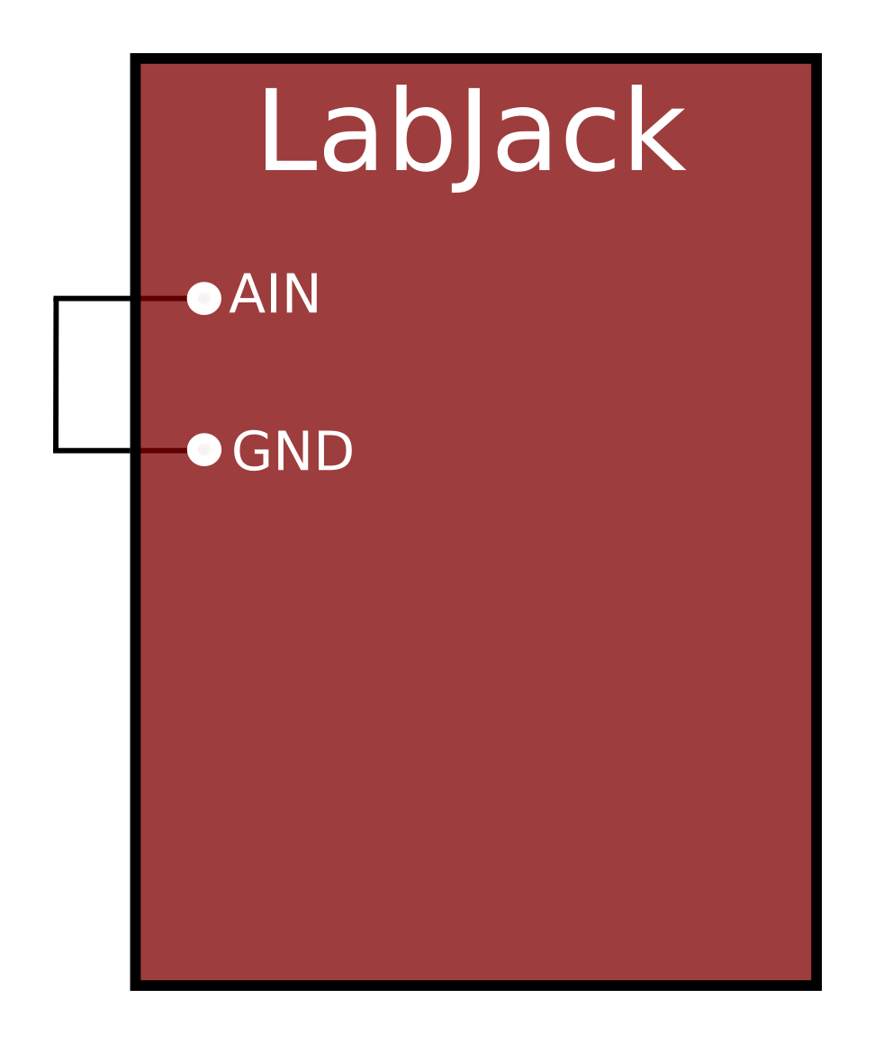
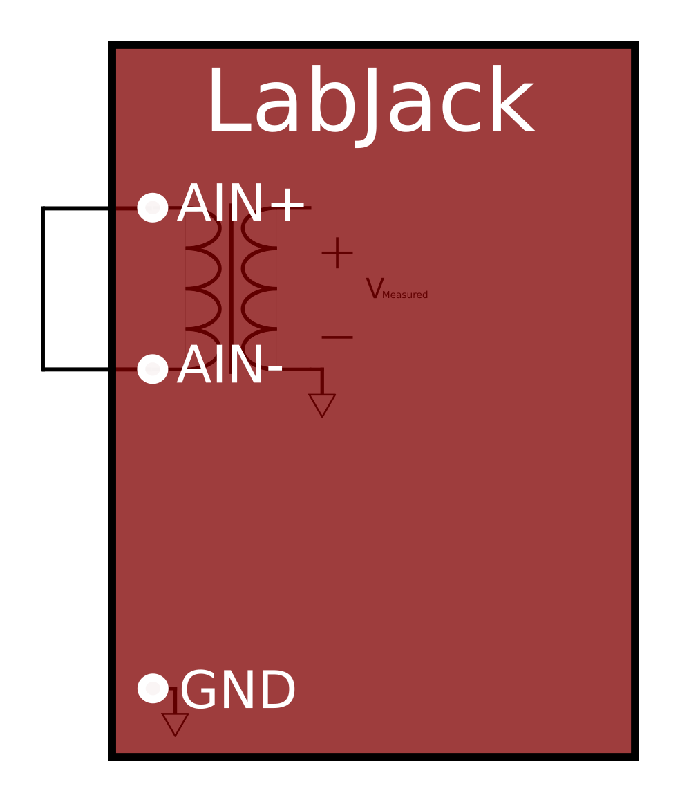
Ground / 0.0 V Test
Securely clamp a jumper wire from GND to AINx and observe the readings. For LabJack devices with isolated inputs, you should instead connect a jumper wire between AINx+ and AINx- terminals to take a 0.0 V measurement.
Accuracy
Readings should be 0.0 V, within the accuracy spec for the device:
U3-HV (±10 V range, HV channels): -0.027 to +0.027 volts
U3-LV/HV (0-2.4 V range, LV channels*): -0.0032 to +0.0032 volts
U6/U6-Pro (±10 V range): -0.002 to +0.002 volts
UE9 (±5 V range): -0.005 to +0.005 volts
T4 (±10 V range, HV channels): -0.027 to +0.027 volts
T4 (0-2.5 V range, LV channels*): -0.0032 to +0.0032 volts
T7/T7-Pro (±10 V range): -0.002 to +0.002 volts
T8 (±9.6 V range): -0.001 to +0.001 volts
*0.0 (GND) is not a good test point for the low voltage analog inputs (FIO/EIO) on the U3 and T4, as their span might not include all the way down to 0.000 volts. The most likely solution is to apply a test voltage and use a high accuracy DMM to determine the actual value for comparison.
Noise
The noise level of most (1 standard deviation) readings should be similar to the documented effective or RMS noise level. Watch a number of readings and note the voltage variance level that includes most readings.
U3-HV (±10V range, HV channels): 5 mV/count, ±1 counts of noise
U3-LV/HV (0-2.4V range, LV channels*): 0.6 mV/count, ±1 counts of noise
U6 (±10V range, Resolution Index 8): 37 µV
U6-Pro (±10V range, Resolution Index 9): 26 µV
UE9 (±5V range,Resolution Index 17): 44 µV
T4 (±10V range, HV channels, Resolution Index 5): 5 mV/count, ±1 counts of noise
T4 (0-2.5V range, LV channels*, Resolution Index 5): 0.6 mV/count, ±1 counts of noise
T7 (±10V range, Resolution Index 8): 37 µV
T7-Pro (±10V range, Resolution Index 9): 26 µV
T8 (±9.6 V range, Resolution Index 16): 9 µV
*0.0 (GND) is not a good test for the low voltage analog inputs (FIO/EIO) on the U3 and T4, as their span might not include all the way down to 0.000 volts. For the U3, the internal temperature sensor (channel 30) is a sufficiently quiet internal analog input signal, allowing you to see the inherent noise level of your U3. The UD driver converts these readings do degrees K, so expect 0.2 K per count, or divide degrees K by 350 to get a rough conversion to raw volts. For the T4, use an analog output (e.g. DAC0) set to 2.0 volts for a test signal with low enough noise level.
For the U6 and T-series devices, there are noise testing applications available for Windows.
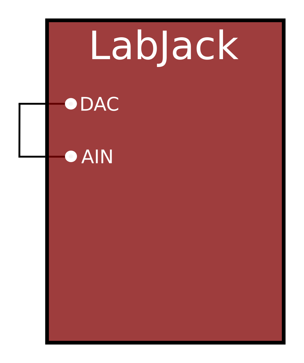
DAC Test
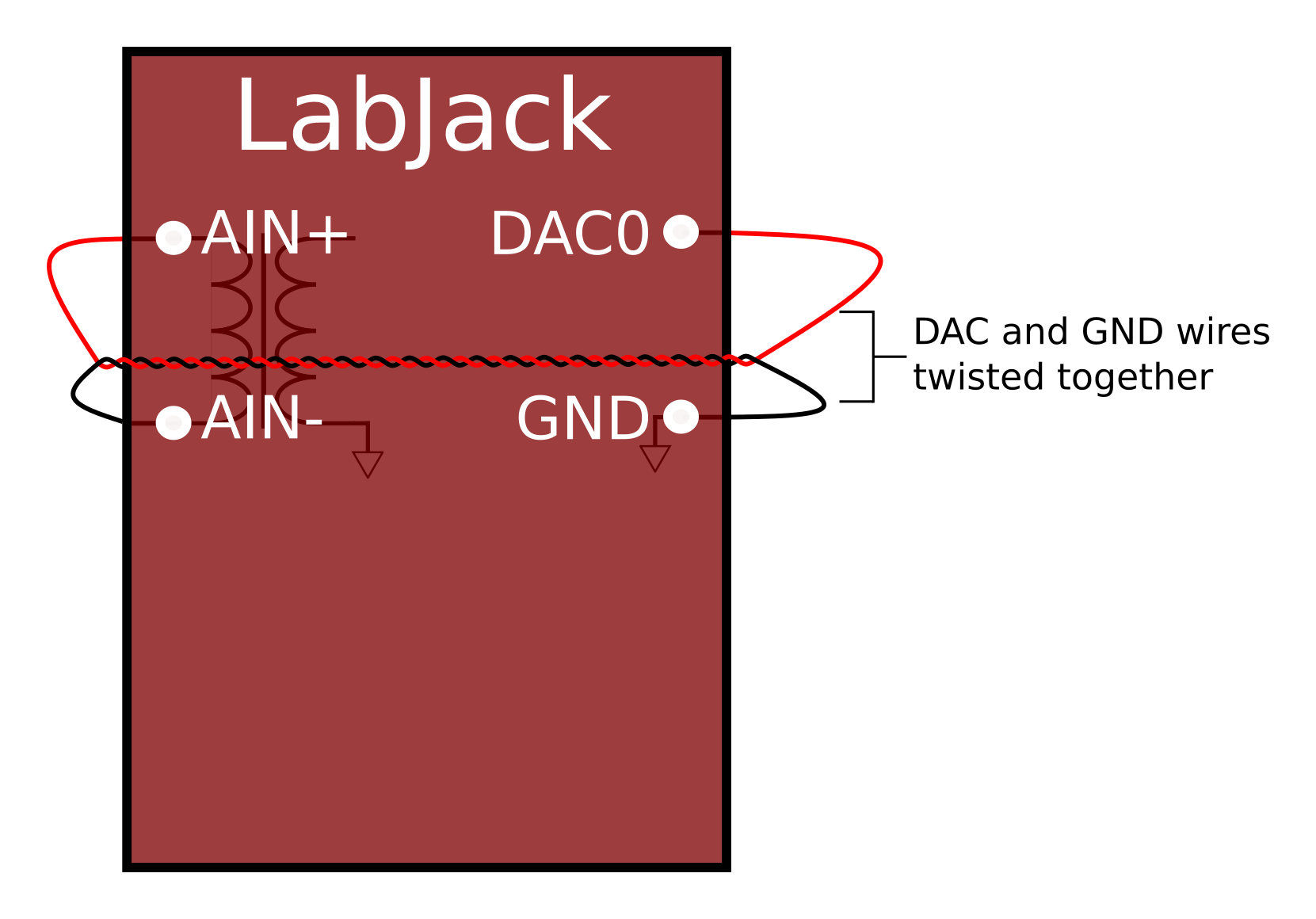
The DAC output terminals that are found on all LabJack devices can be used to verify AIN operation at voltages other than 0.0V. DAC output voltages can be updated using the Dashboard in Kipling (for T-series devices) or the Test panel in LJControlPanel (for UD devices).
Non-isolated Inputs
Securely clamp a jumper wire from DACx to AINx(+). For LabJack devices with isolated inputs, you must also connect a jumper wire from GND to AINx-, and we suggest twisting the DACx and GND jumper wires together to form a twisted pair. This can help reject unwanted noise.
Observe the AINx readings as you adjust DACx. Vary DACx from 0.5 to 4.5 volts and confirm AINx reads a similar value.
Flexible IO on devices such as the U3 and T4 have an analog input range that is smaller than 0-5V, and out of range DAC voltages will be read as the max input value.
Differential Test
Differential tests should not be necessary unless you are trying to configure differential measurements. See the tests and other related information in the Differential Readings App Note.
Mux80 Extended Channels
The Mux80 is added to a U6(Pro)/UE9/T7(Pro) to create analog inputs 48 through 127. These extended channels behave the same as normal channels, so testing is the same as above, but here are a couple tips:
-
LJControlPanel does not support the extended channels, so for UD devices use LJLogUD to view readings from any analog input.
-
Extended channels do no show up on the Dashboard or Analog Inputs tab in Kipling, so for T-series devices use the Register Matrix in Kipling or use LJLogM.
-
AIN48-AIN127 appear on the X2-X5 connectors of the Mux80. If using CB37s to provide screw terminal connections, you must use Table 1 of the Mux80 Datasheet to find where each extended analog input appears on the CB37s.
-
Unlike normal analog inputs, differential pairs for extended analog inputs are not positive=even and negative=even+1. See the Mux80 Datasheet to determine the correct channel numbers for positive/negative differential pairs.
Troubleshooting Tips
These tips might lead you to a solution, might lead you to the conclusion you have a problem, or might provide clues that will help us understand your issue.
-
Update to the latest version (beta if available) of our software so you are using the same as us.
-
Update to the latest firmware (beta if available) so you are using the same as us.
-
T-series: Use the Device Updater tab in Kipling.
-
UD (U3, U6, UE9): Use LJSelfUpgrade for Windows.
-
-
Reset device to factory condition. This eliminates issues due to custom analog configuration, AIN-EF configuration, and Lua scripts.
-
Securely install reset jumper
U3-LV or U3-HV: SPC to FIO6
U6: SPC to FIO2
UE9: SCL to FIO2
T4: SPC to FIO6
T7: SPC to FIO2
T8: SPC to FIO2 -
Power cycle the device.
-
Remove reset jumper.Power cycle the device.
-
-
Remove all connections except power & communication as needed (e.g. USB). This includes ANY and ALL connections to screw terminals or DB15/DB37 ports. Then just use 1 or 2 small jumper wires as needed for testing. This eliminates issues caused by other user connections.
-
Confirm power supply is 4.75 to 5.25 volts. Use a DMM to measure VS to GND (see tip 7 below), and/or add an extra jumper wire to connect VS to some unused analog input.
-
Close all other software and just run Kipling (T-series devices) or LJControlPanel (UD devices). This eliminates issues due to unknown software. Make sure you only run 1 LabJack related program at a time.
-
Make sure any applicable screw terminals are securely clamped on a conductor. Click for more about screw terminals.
-
For the U6-Pro and T7-Pro, compare readings from the high-speed converter (ResolutionIndex 1-8) to readings from the high-resolution converter (ResolutionIndex 9-12). They should be very similar and both should be within spec.
-
Compare your LED behavior to normal LED behavior examples.
-
Contact LabJack Support for further help. Provide confirmation that you did the above 9 items in order, and let us know if all went as described.