Overview
This page discusses the capabilities and usage of analog input features and characteristics specific to the T4.
For topics that apply to all devices such as: Common Uses, AIN Extended Features, Floating Inputs, Calibration, Volts vs Binary, Troubleshooting, and Accessories see: 14.0 Analog Inputs
Feature Highlights
|
Analog Inputs: |
4 high-voltage (±10V, AIN0-AIN3)
|
|
Voltage Ranges: |
±10 V (AIN0-AIN3)
|
|
Resolution: |
12-bit |
|
Max Data Rate: |
50000 samples/second in stream mode |
|
Sampling Modes: |
Single-ended |
Available AIN Channels
The T4 exposes:
-
Some AINs on the screw terminals.
-
Additional AINs on a DB15.
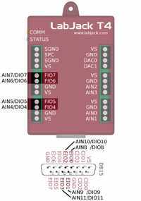
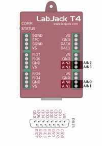
The LabJack T4 has up to 12 built-in analog inputs, readable as AIN0-AIN11:
-
AIN0-AIN3 are dedicated ±10 volt inputs:
-
Available on screw terminals AIN0-AIN3.
-
Always ±10 volt analog inputs.
-
-
AIN4-AIN7 are flexible 0 to +2.5 volt inputs:
-
Available on screw terminals FIO4-FIO7.
-
Configurable to be digital inputs/outputs. See "Flexible I/O" below.
-
-
AIN8-AIN11 are flexible 0 to +2.5 volt inputs:
-
Available on the DB15 connector EIO0-EIO3.
-
Configurable to be digital inputs/outputs. See "Flexible I/O" below.
-
Flexible I/O
Flexible I/O are I/O ports that can be configured as analog inputs, or digital IO. The function of the flexible IO ports can be configured in the following ways:
-
Reading from AIN# registers - When reading from AIN# registers the corresponding line will automatically be set to analog.
-
Reading from DIO# registers - When reading form the DIO registers the corresponding line will automatically be set to digital.
-
Explicit configuration - The flexible IO ports can be configured as a group or individually by setting the corresponding bits in DIO_ANALOG_ENABLE. The DIO_ANALOG_ENABLE is a DIO bitmask register, see here for details: 13.0 Digital I/O
These registers set the signal type of the Flexbile I/O for command-response and stream.
Resolution
The T4 can adjust the resolution of its analog inputs.
A higher resolution index results in lower noise and higher effective resolution at the expense of increases sampling times.
In command-response mode, each channel has its own resolution setting. In stream mode, all channels must use the same resolution.
When the resolution index is set to zero, the device will select the best resolution for the situation. The best resolution will depend on the operating mode and sampling rate. Check the register descriptions below for details.
These registers set the Analog Input resolution for command-response readings. For stream, refer to the "Streaming AIN" section below.
Settling
The settling registers control the time from a step change in the input signal to when the signal is sampled by the ADC. A step change occurs when the internal multiplexers change from one channel to another. In general, more settling time is required as resolution or source impedance are increased.
The value 0 sets automatic settling, which is recommended for most applications. This "auto" settling ensures that the device meets specifications at any gain and resolution for source impedance up to at least 1000 ohms.
For a more in depth discussion of settling see: Analog Input Settling Time
These registers set the settling time for command-response readings. For stream, refer to the "Streaming AIN" section below.
Streaming AIN
Stream allows for automatic and high-speed data collection. See 3.2 Stream Mode for details. Some stream configurations override the normal AIN configurations:
-
Use STREAM_SETTLING_US instead of AIN_SETTLING_US.
-
Use STREAM_RESOLUTION_INDEX instead of AIN_RESOLUTION_INDEX.
Command-Response while Streaming
Command-response can be performed while a stream is active. Commands sent while stream is running will take longer to execute than normal. The magnitude of the slowdown increases with stream rate.
If any of the channels in the scan list are analog inputs, then streaming needs exclusive control of the analog input system. The result is that analog inputs (including the internal temperature sensor) cannot be read via command-response while a stream is active.
If the stream scan list does not contain any analog inputs, then the AIN system is free to be used by command-response.
For more information about stream see: 3.2 Stream Mode
Operation
The T4 has a single analog to digital converter (ADC) and two separate channel selection systems. The ADC is a 12-bit successive approximation register (SAR) with an input range of 0 to 2.5 V. Each channel selection system must convert the incoming signals to match that input range. The two selection systems each specialize in either HV or LV inputs:
-
HV Lines - The HV lines use a resistive network to divide and shift the ±10V range to match the ADC’s input range. An op-amp buffers the signal and finally a multiplexor selects which channel will be sent to the ADC. The resistive network will cause floating signals to read about 1.4V, for more information about floating signals, see here: Floating/Unconnected Analog Inputs
-
LV Lines - The LV lines pass through some protection circuity then into a multiplexor. The range is already matches that of the converter, so no shifting is necessary.