Communication Modes
Communication between the host computer and a T-series device occurs using one of two modes:
1. Command-response
Command-response mode is appropriate for most applications. In command-response mode, the host sends a command data packet, to which the T-series device sends a response data packet.
2. Stream
Stream mode is when the device collects periodic sampling events automatically. Collected data is stored in the device's memory until it retrieved by the host application. The LJM library stream functions simplify data collection from T-series devices. Not all functionality is supported in stream mode.
For more information about command-response and stream, see 3.0 Communication.
Note: These specs are generated using a LabVIEW program that reads data from a device in a simple while(1) loop. Additionally, we used a PC running Windows with a fairly average Intel CPU. We have found the performance of LabVIEW to be very similar to C, C++, and other compiled languages and have therefore chosen LabVIEW to collect these data rates. If an application requires precise timing of CR packets we suggest doing additional research and replicating these results for the system being used.
Figure A1.1depicts the two operating modes.
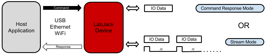
The use of a particular mode will depend on functionality and the hardware response time required by the end application.
Command-Response Data Rates
All communication performed with T-series devices is accomplished using the Modbus TCP protocol, thus allowing direct communication with the device via low-level TCP commands. As an alternative, the LJM library may be used as a higher level communications layer for added convenience and minimal additional overhead. Tables A.1.1 to A.1.3 list expected communication overhead times associated with Modbus TCP and LJM Library communication options. Tables A.1.1 and A.1.2 times are the same on the T4/T7, and were measured on a T7. Communication times for the T8 can be found in Table A.1.3.
Table A.1.1. Typical communication overhead using direct Modbus TCP with the T4/T7.
|
|
USB (High-High) |
USB (Other) |
Ethernet |
WiFi |
|---|---|---|---|---|
|
|
[ms] |
[ms] |
[ms] |
[ms] |
|
No I/O Overhead |
0.6 |
2.1 |
1.0 |
6.5 |
|
Read All DI |
0.7 |
2.2 |
1.1 |
6.6 |
|
Write All DO |
0.7 |
2.2 |
1.1 |
6.6 |
|
Write Both DACs |
0.7 |
2.2 |
1.1 |
6.6 |
Table A.1.2. Typical communication overhead using the LJM Library with the T4/T7.
|
|
USB (High-High) |
USB (Other) |
Ethernet |
WiFi |
|---|---|---|---|---|
|
|
[ms] |
[ms] |
[ms] |
[ms] |
|
No I/O Overhead |
0.6 |
2.2 |
1.1 |
6.7 |
|
Read All DI |
0.7 |
2.3 |
1.2 |
6.8 |
|
Write All DO |
0.7 |
2.3 |
1.2 |
6.8 |
|
Write Both DACs |
0.7 |
2.3 |
1.2 |
6.8 |
Table A.1.3. Typical communication overhead using the LJM Library with the T8.
|
|
USB (High-High) |
USB (Other) |
Ethernet |
|---|---|---|---|
|
|
[ms] |
[ms] |
[ms] |
|
Read All DI |
0.18 |
0.18 |
0.265 |
|
Write All DO |
0.19 |
0.19 |
0.285 |
|
Write Both DACs |
0.19 |
0.19 |
0.295 |
The times shown in tables A.1.2 and A.1.3 were measured using a LabVIEW program running on Windows where all read and write operations are conducted with a single LJM_eNames() call. The LJM_eNames() functions is used to minimize the number of Modbus packets sent from the host (one packet per command/response set). The test program executes one of the listed tasks within a loop for a specified number of iterations, over a 1-10 second period. The overall execution time is divided by the total number of iterations, providing the average time per iteration for each task. The execution time includes LabVIEW overhead, LJM library overhead, Windows overhead, communication time (USB/Ethernet/WiFi), and device processing time.
A "USB high-high" configuration means the T-series device is connected to a high-speed USB2 hub which is then connected to a high-speed USB2 host. Even though the Tx is not a high-speed USB device, such a configuration does often provide improved performance. Typical examples of "USB other" would be a Tx connected to an old full-speed hub (hard to find) or more likely the Tx is connected directly to the USB host (your PC) even if the host supports high-speed.
For more information, see this app note: High Speed Command-Response Sample Rates
Preemptive Operating Systems and Thread Priority
It is important to understand that Linux, Mac OS X, and Windows are generally "best-effort" operating systems and not "real-time", meaning that the listed CR speeds can vary based on each individual computer, the hardware inside of it, its currently enabled peripherals, current network traffic, strength of signal, design of the application software, other running software, and many more variables [1].
USB and Ethernet
These times are quite predictable. Software issues mentioned above are important—but, in terms of hardware, the times will be consistent. The device communication does not consume a major portion of total USB or Ethernet bandwidth. Therefore, the overhead times listed are typically maintained even with substantial activity on the bus.
WiFi - T7-Pro
WiFi latency tends to vary more than USB or Ethernet latency. With a solid connection, most WiFi packets have an overhead of 3 to 8 ms, but many will take longer. For example, a test was done in a typical office environment of 1000 iterations that produced an average time of 7.0 ms. The results were:
-
92% of the packets took 3-8 ms,
-
99% took < 30 ms,
-
and 3 packets took 300 ms.
All WiFi tests were done with an RSSI between -40 (very strong) and -70 (good). An RSSI less than -75 generally reflects a weak connection, causing a greater number of packets retries. An RSSI greater than -35 reflects a very strong connection, typically within a few feet of the access point. This also results in a greater numbers of retries due to saturation of the RF signal.
ADC Conversions
Analog to digital conversions (ADC) will increase the command-response time depending on the number of channels, the input gain (T7), and the resolution index being used. The tables linked in the sections below list conversion times for various settings when reading a single analog input channel. The total command-response time (CRT) when reading analog inputs is equal to the overhead time from tables A.1.1, A.1.2 and A.1.3 added to the conversion times for the requested channels:
CRT (milliseconds) = overhead + (#AINs * AIN Sample Time)
T4 AIN Sample Time
See the tables in Section A-3-1-2: T4 Noise and Resolution.
T7 AIN Sample Time
See the tables in Section A-3-2-2: T7 Noise and Resolution.
T8 AIN Sample Time
See the tables in Section A-3-3-2: T8 Noise and Resolution.