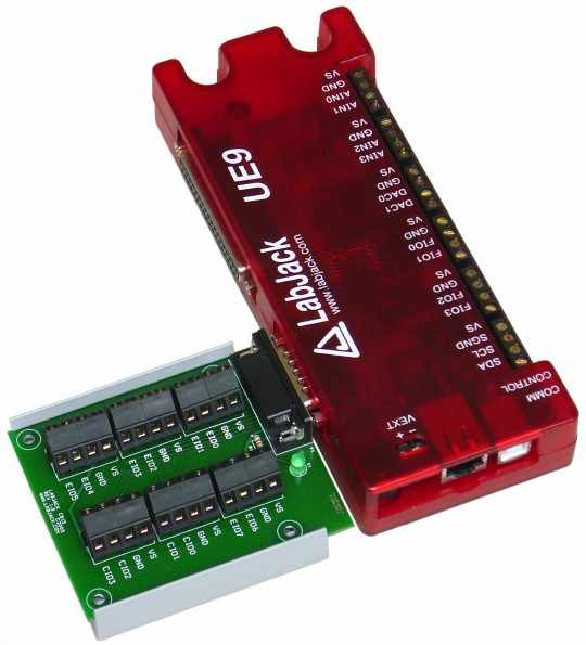
The CB15 terminal board connects to the DB15 connector on applicable LabJacks (not the U12). It provides convenient screw terminal access to the 12 digital I/O available on the DB15 connector. The CB15 is designed to connect directly to the LabJack (see image below), or can connect via a standard 15-line 1:1 male-female DB15 cable (not included).
The green LED on the CB15 is directly powered by the 5-volt supply (Vs) from the LabJack, so it should be lit whenever the CB15 is connected to a powered LabJack.
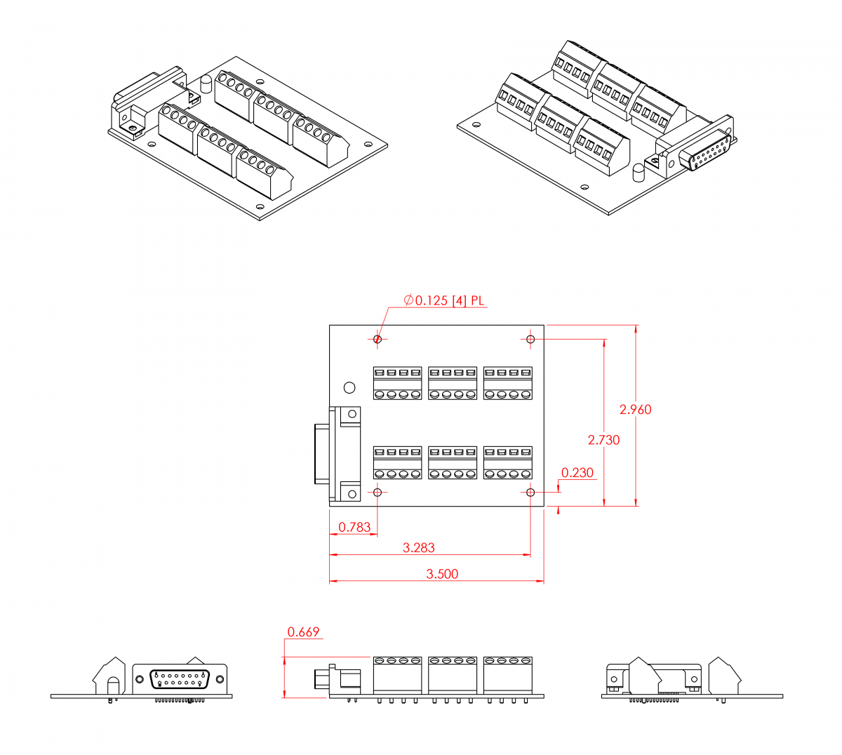
The CB15 PCB can be mounted to the LJ-Snap2D. The LJ-Snap2D is DIN rail mountable using TE Connectivity part #TKAD (not included).
For more information about the I/O lines, see the User’s Guide for the applicable LabJack. Here are a few useful links:
-
T-Series Section 13.0 (Digital I/O)
-
T-Series Section 13.1 (Flexible I/O)
-
T-Series Section 17.0n (DB15)
-
U3 Section 2.5 (Flexible I/O)
-
U3 Section 2.8 (Digital I/O)
-
U3 Section 2.11 (DB15)
-
U6 Section 2.8 (Digital I/O)
-
U6 Section 2.12 (DB15)
-
UE9 Section 2.9 (Digital I/O)
-
UE9 Section 2.13 (DB15)
Table 1. DB15 Pinouts and Names
|
Pin # |
Pin Name |
|
Pin # |
Pin Name |
|
1 |
VS |
|
9 |
CIO0 |
|
2 |
CIO1 |
|
10 |
CIO2 |
|
3 |
CIO3 |
|
11 |
GND |
|
4 |
EIO0 |
|
12 |
EIO1 |
|
5 |
EIO2 |
|
13 |
EIO3 |
|
6 |
EIO4 |
|
14 |
EIO5 |
|
7 |
EIO6 |
|
15 |
EIO7 |
|
8 |
GND |
|
|
|
Notes:
1. LJ-Snap2D not shown.
Common neutral format CAD models are provided below. Right-click and select the "Save link as..." option to download STEP files.