Push-pull vs. Open-collector vs. Mechanical Switch Input
The most basic connection to a LabJack digital input is a push-pull (also called driven) signal. With a push-pull signal the source is driving (low-impedance) a high voltage for logic high and zero volts for logic low. This is in contrast to BJT/Open-collector output which will switch between open and low (NPN) or open and high (PNP), or a dry contact/switch signal such as a reed switch, SPST switch, or mechanical relay.
Push-pull Connections
Unless the logic high is too high, a push-pull signal can be connected directly to one of the LabJack's digital I/O pins. If the signal is at a voltage greater than the maximum tolerated voltage of the LabJack I/O, the LJTick-Divider or the RB12 with appropriate modules can be used to drop the voltage to a tolerable level. Most LabJack digital IO are TTL level tolerant; detailed specifications can be found in Appendix A of each device's datasheet.
The other consideration with basic push-pull signals is the ground connection. If the signal is already known to have a common ground with the LabJack, then no additional ground connection is necessary. If the signal does not have a common ground with the LabJack, then the signal ground can be connected to LabJack GND. If there is any uncertainty about the relationship between signal ground and the LabJack ground, e.g. possible common ground through AC mains, then a ground connection with a ~10 ohm series resistor is generally recommended.
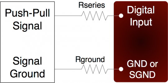
Figure 1 shows typical connections. Rground is typically 0-100 ohms. Rseries is typically 0 Ohms (short-circuit) for 3.3/5 volt logic, or 22K ohms (max) for high-voltage logic. Note that an individual ground connection is often not needed for every signal. Any signals powered by the same external supply, or otherwise referred to the same external ground, should share a single ground connection to the LabJack if possible.
When dealing with a new sensor, a push-pull signal is often incorrectly assumed when in fact the sensor provides an open-collector signal as described in the Open-Collector App Note.
Clamping Higher Voltage Push-pull Signals
Another option to handle >5V push-pull signals is to use a series resistor to limit current into the I/O, and leveraging the built-in device protection (barrier and Schottky diodes) to clamp the voltage at a tolerable level. On the LabJack digital I/O, diodes will clamp the voltage between roughly GND and VS. The U12 starts clamping at VS+0.3, while the U3, U6, UE9, T4, T7, and T8, start clamping at a fixed 5.8 volts. Further information can be found in Appendix A of each device's datasheet. If a 24 volt signal is connected through a 15kΩ series resistor ~19 volts will be dropped across the resistor, resulting in a current of 1.3mA, which is no problem for any LabJack devices. The series resistor should be 15kΩ or less to make sure the voltage on the I/O line when low is pulled below the logic-low threshold of LabJack devices. A 15kΩ resistor is usually a great solution for all voltages up to 48 volts.