This app note is written for all LabJacks except the U12. The U12 has 1MΩ pull-downs, rather then the 100 kΩ pull-ups on all other devices.
Open-collector (also called open-drain, NPN, or PNP) is a very common type of digital signal. Rather than providing a low-impedance 5 volts and ground like a push-pull signal, an open-collector signal provides open and ground. This type of signal can be thought of as a switch connected to ground. The various terms are used somewhat loosely, and often all variations are simply called "open-collector", but following is the most common usage:
Open-collector = NPN = Changes between open and low.
Open-drain = PNP = Changes between open and high.
NPN
Since the LabJack digital inputs have 100 kΩ internal pull-up resistors that hold them high when nothing is connected, an NPN signal can typically be connected directly to the input.
-
When the NPN signal is inactive, it is not driving any voltage and the pull-up resistor pulls the digital input to logic high.
-
When the NPN signal is active, it drives 0 volts which overpowers the pull-up and pulls the digital input to logic low.
-
Sometimes an external pull-up (e.g. 4.7 kΩ from Vs to digital input) will be installed to increase the speed and strength (i.e. more immune to EMI) of the logic high condition.
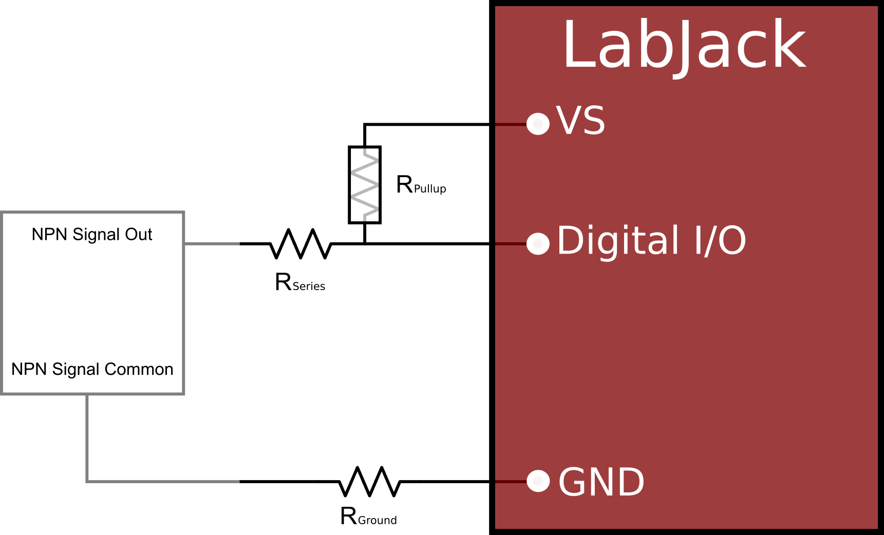
Rground is typically 0 Ω, but occasionally a series resistor is used to prevent from large currents flowing into ground.
Rseries is typically 0 Ω, unless needed to create an RC low-pass filter or if needed to limit current for voltages substantially higher than 5 volts. If there is some uncertainty about whether the signal is actually open-collector or could drive a voltage beyond 5 volts, use an Rseries of 22 kΩ as discussed in the Driven Signals App Note.
Rpullup (external pull-up resistor) is typically not required, but is used much more often than Rground and Rseries. A 4.7 kΩ is sometimes added if a stronger pull-up is needed to avoid false lows due to EMI. The only downside to adding this external pull-up is that VS has to source a little extra current and the NPN switch has to sink this extra current, but it is only about 1mA with 4.7 kΩ.
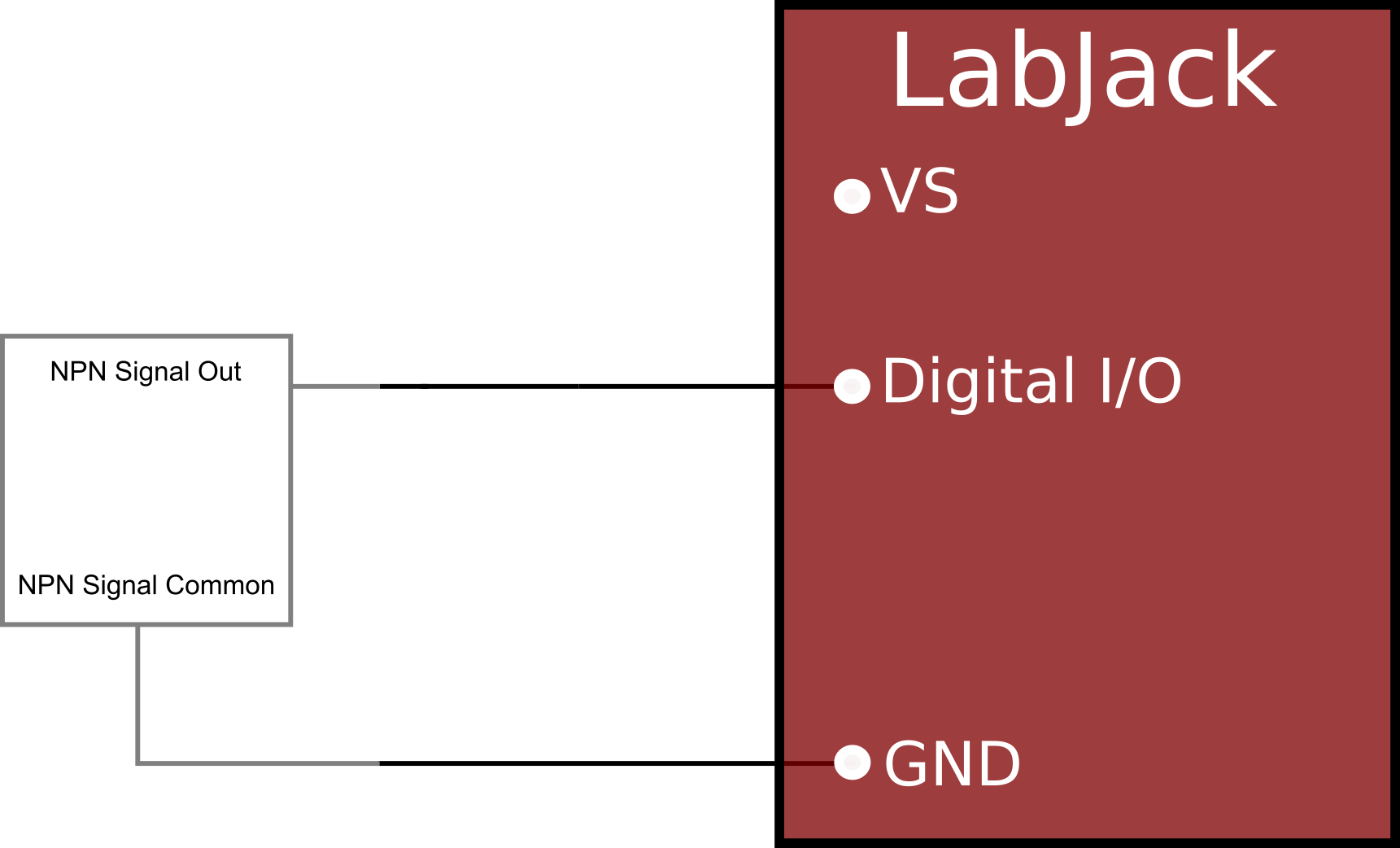
Without the optional resistors, Figure 1 simplifies to Figure 2, which is the most common connection.
PNP
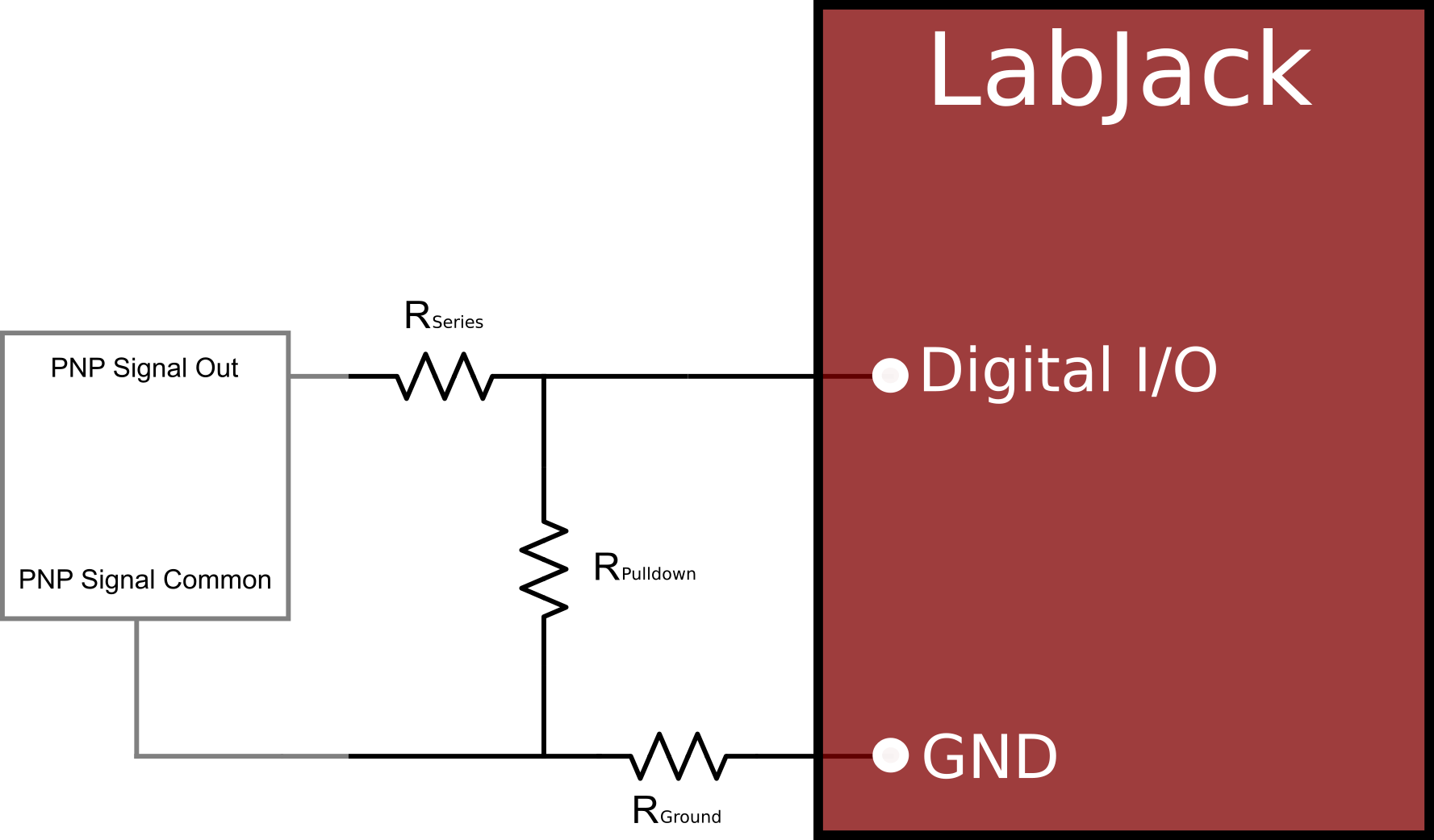
For a PNP switch, Rpulldown (rather than Rpullup) is required from the digital input to GND. Another option to condition a PNP output is to use an LJTick-Divider.
-
When the PNP signal is active, it drives a logic high output condition that should hold the digital input to a logic high.
-
When the PNP signal is inactive, it is not driving any voltage. A pulldown resistor is required to overpower the internal 100 kΩ pull-up of the digital input and hold the digital input low.
-
The pulldown resistor must be sized small enough so that the PNP output can still drive a logic high condition, but big enough to overpower the digital input pullup resistor. Typically a pulldown resistor of roughly 4.7 kΩ is used.
-
Note that if the PNP high voltage is greater than 5 volts, Rseries is also needed to protect the digital input. Rseries combines with Rpulldown to create a voltage divider (and also the internal 100 kΩ pull-up to 3.3 V, but this can be ignored for a rough calculation).
-
Rseries=10 kΩ and Rpulldown=4.7 kΩ, results in a 12 V input signal dividing down to ~3.8 volts.
-
Rseries=22 kΩ and Rpulldown=4.7 kΩ, results in a 24 V input signal dividing down to ~4.3 volts.
-
Other Notes
-
Our oldest device, the U12, has a 1 MΩ pull-down rather then the 100 kΩ pull-up on each digital line. We recommend always using a 4.7 kΩ pull-up resistor (to +5V) with NPN signals or a 4.7 kΩ pull-down resistor (to GND) with PNP signals.
-
Various mention is made above to protecting from voltages greater than 5 volts. The actual limits can be found in Appendix A of each device's datasheet. The U12 starts clamping at VS+0.3, while the U3, U6, UE9, T4, T7, and T8 start clamping at a fixed 5.8 volts, so an added series resistor should be considered for voltages beyond those levels.
-
Note that an individual ground connection to the LabJack is often not needed for every signal. Any signals powered by the same external supply, or otherwise referred to the same external ground, should share a single ground connection to the LabJack whenever possible.