As of this writing, this app note applies to the U3, U6, UE9, T4, T7 and T8.
Basic Operation
To detect whether a mechanical switch is open or closed, connect one side of the switch to the LabJack's ground and the other side to a digital input.
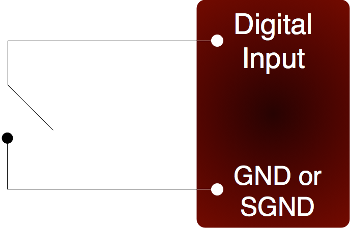
When the switch is open, the internal 100 kΩ pull-up resistor will pull the digital input to about 3.3 volts (logic high). When the switch is closed, the ground connection will overpower the pull-up resistor and pull the digital input to 0 volts (logic low). Since the mechanical switch does not have any electrical connections, besides to the LabJack, it can safely be connected directly to GND, without using a series resistor or SGND.
Switch Bounce
When a mechanical switch is closed (and even perhaps when opened), it will bounce briefly and produce multiple electrical edges rather than a single high/low transition. For many basic digital input applications, this is not a problem as the software can simply poll the input a few times in succession to make sure the measured state is the steady state and not a bounce. For applications using timers or counters, however, this can be a problem. The hardware counters, for instance, are very fast and will increment on all bounces. Some solutions to this issue are:
-
Software Debounce: If it is known that a real closure cannot occur more than once per some interval, then software can be used to limit the number of counts to that rate.
-
Firmware Debounce: See your device timer documentation: U3/U6/UE9/T-Series
-
Active Hardware Debounce: Integrated circuits are available to debounce switch signals. This is the most reliable hardware solution. See the MAX6816 (maxim-ic.com) or EDE2008 (elabinc.com).
-
Passive Hardware Debounce: A combination of resistors and capacitors can be used to debounce a signal. This is not foolproof, but works fine in most applications.
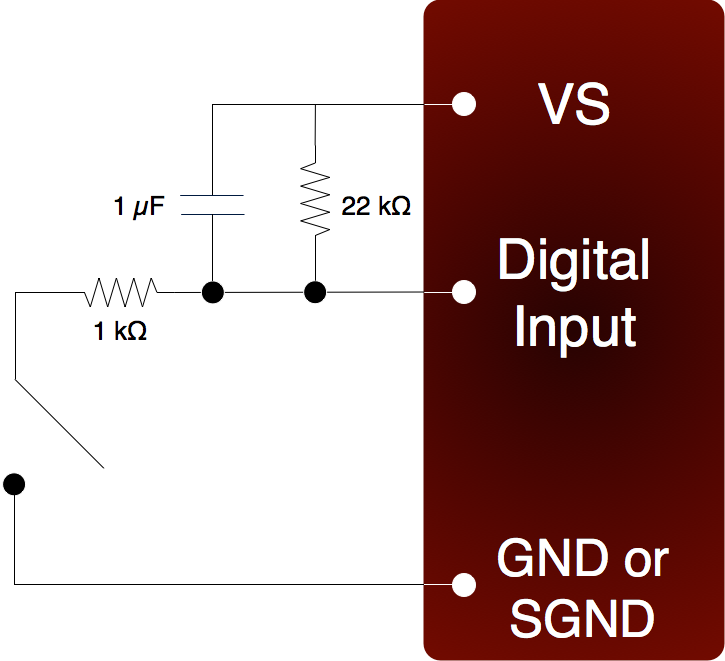
Figure 2 shows one possible configuration for passive hardware debounce. First, consider the case where the 1 kΩ resistor is replaced by a short circuit. When the switch closes it immediately charges the capacitor and the digital input sees logic low, but when the switch opens the capacitor slowly discharges through the 22 kΩ resistor with a time constant of 22 ms. By the time the capacitor has discharged enough for the digital input to see logic high, the mechanical bouncing is done. The main purpose of the 1 kΩ resistor is to limit the current surge when the switch is closed. 1 kΩ limits the maximum current to about 5 mA, but better results might be obtained with smaller resistor values.
EMI
When the switch is open, strong electromagnetic interference (EMI) can induce voltage on the wires and cause brief incorrect readings. For example, the T4 & T7 have internal 100k pull-ups to ~3.3 volts. This is sufficient for most applications, but if strong EMI is a concern, external pull-up resistors might be added from the digital input to VS (~5 volts). A 4.7k resistor is common, and just means that when the switch is closed it has to be able to handle 1 mA of current.
U12 Notes
The above information was not written for the U12. Following is an extra note for our original U12 device which was released in 2001. See the U12 Datasheet for more details.
Pull-downs: Most newer devices have pull-up resistors that hold digital inputs high when floating, but the U12 has pull-down resistors that hold digital inputs low when floating. Unlike the 1st figure above, on the U12 a switch would connect to a digital input and +5V.