Thermocouple Theory
There are many places to read about thermocouple theory, including the Thermocouple page on Wikipedia. This page covers the essential theory for measuring thermocouples with LabJack hardware.
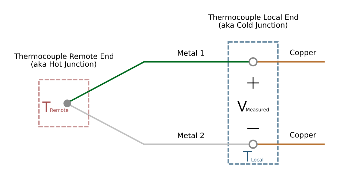
A thermocouple has two wires made from dissimilar metal. The wires are shorted at one end (the remote end) and due to the Seebeck effect a voltage is produced at the other end (the local end, aka cold junction). The cold junction is typically at the screw terminals on a LabJack DAQ or CB37.
A thermocouple produces a voltage (VMeasured) that is related to the difference in temperature between the remote end (TRemote) and local end (TLocal)[1].
You can acquire VMeasured and TLocal using a LabJack device, then use them to calculate TRemote[2].
Many years ago, the cold junction would be placed in an ice bath to maintain 0 °C. No thermocouple voltage will be generated at 0 °C, thereby eliminating cold junction effects. Fortunately, modern electronics and processing power make it easy to account for any cold junction temperature without an ice bath.
Should I Use Thermocouples?
Common reasons to use thermocouples:
-
Wide range (very low or very high temperatures).
-
Desirable physical properties (i.e. form factor).
-
Low cost.
Reasons not to use thermocouples:
-
Poor accuracy.
-
Difficult to use.
Thermocouple Complications
-
Small Output Voltage: Thermocouples generate a low voltage signal (e.g., around 40 µV/°C for K-type), which can make achieving high temperature resolution challenging without adequate amplification and resolution capabilities from the DAQ.
This is the reason some devices such as the U3/T4 require an LJTick-InAmp, whereas other devices have the necessary resolution and amplification built-in.
-
Complex Math: The relationship between temperature and voltage in a thermocouple is non-linear, requiring complex math for accurate conversion[1]. In addition, calculations for cold junction compensation (CJC) must be done[2].
LabJack’s UD and LJM libraries provide convenient functions to handle voltage to temperature conversion. Some T-series devices also have extended functionality (AIN_EF) to handle the conversion and return a temperature reading directly from the device.
-
Cold Junction Errors: Any error in measuring the temperature of the cold junction will result in about the same error in the calculated thermocouple temperature[2].
If connecting to a breakout board, such as the CB37, rather than directly to the LabJack terminals, you might want to use an external silicon based sensor such as the LM34CAZ to measure the cold junction temperature.
-
Poor Inherent Accuracy: Variabilities in thermocouple material can introduce errors. International standards such as IEC 584-2 specify tolerances for these errors. These are typically ±1.0 to ±2.5 °C at moderate temperatures, but can be as high as ±9.0 °C at 1200 °C.
See the Thermocouple Comparison Table on the thermocouple Wikipedia page
-
Bad Ground Loops: This is a common and complex problem people encounter when using thermocouples. It occurs when bare thermocouple wire is used, or a metal thermocouple probe where one of the thermocouple wires inside is connected to the probe (often called a "grounded" probe). If multiple of these are connected to a common conductor (e.g. a system of connected metal pipes), and connected single-ended to the LabJack, you can get ground loops and unexpected thermocouple junctions.
The typical fix is to use differential inputs with a resistor (100k is typical) from the negative input to GND. As noted in the Differential Readings Application Note, the resistor is sized to be low enough to provide a path for bias currents but high enough to prevent ground loop issues. Differential connections usually prevent this problem, and the T8’s analog inputs with channel-to-channel isolation are a surefire fix.
To avoid this complication, install thermocouples such that this situation cannot occur:
a. Use some sort of substance, between the thermocouple metal and test specimen, that has good thermal conduction but poor electrical conduction. Epoxy, tape, etc.
b. Place the thermocouple near, but not actually touching, the test specimen.
c. Use probes that are called "ungrounded". A very common option.
d. Use thermocouples with an electrically insulating layer between the thermocouple metal and test specimen. One example is the SA1 series of self-adhesive thermocouples from Omega.
-
Ground Offsets: Care must be taken to avoid ground offset errors with single-ended measurements. Error will result if the negative lead of the thermocouple is connected to a GND terminal that is at a different voltage than Ground at the A/D chip. Multiple things have to combine to cause this problem. For more information see the Ground Offsets sections in the CB37 Datasheet and Mux80 Datasheet.
-
EMI Susceptibility: The weak signal generated by thermocouples makes them prone to electromagnetic interference. EMI can easily introduce noise on long thermocouple wires. For example, an arc furnace near the thermocouple could cause noise issues.
Footnotes
[1] The gradient in voltage (from the remote to local end) between the two metals of a thermocouple is proportional to the gradient in temperature (from the remote to local end) of the thermocouple. The math necessary to do voltage-temperature conversion is complicated, but there are well defined approximations available for common thermocouple types using lookup tables or functions that utilize power series expansion. NIST ITS-90 is one common source for lookup tables and functions.
[2] The Seebeck effect, which generates a voltage between thermocouple metals, also generates a voltage where each thermocouple metal transisitions to another metal at the cold junction. This voltage should be accounted for to reduce error, and this is called cold junction compensation (CJC). To perform CJC, the equivalent thermocouple voltage of the cold junction must be calculated from the cold junction temperature (TLocal in Figure 1) and then added to the measured thermocouple voltage (VMeasured in Figure 1). This produces an approximation of the thermocouple voltage at the remote end, which can then be converted to temperature (TRemote in Figure 1).