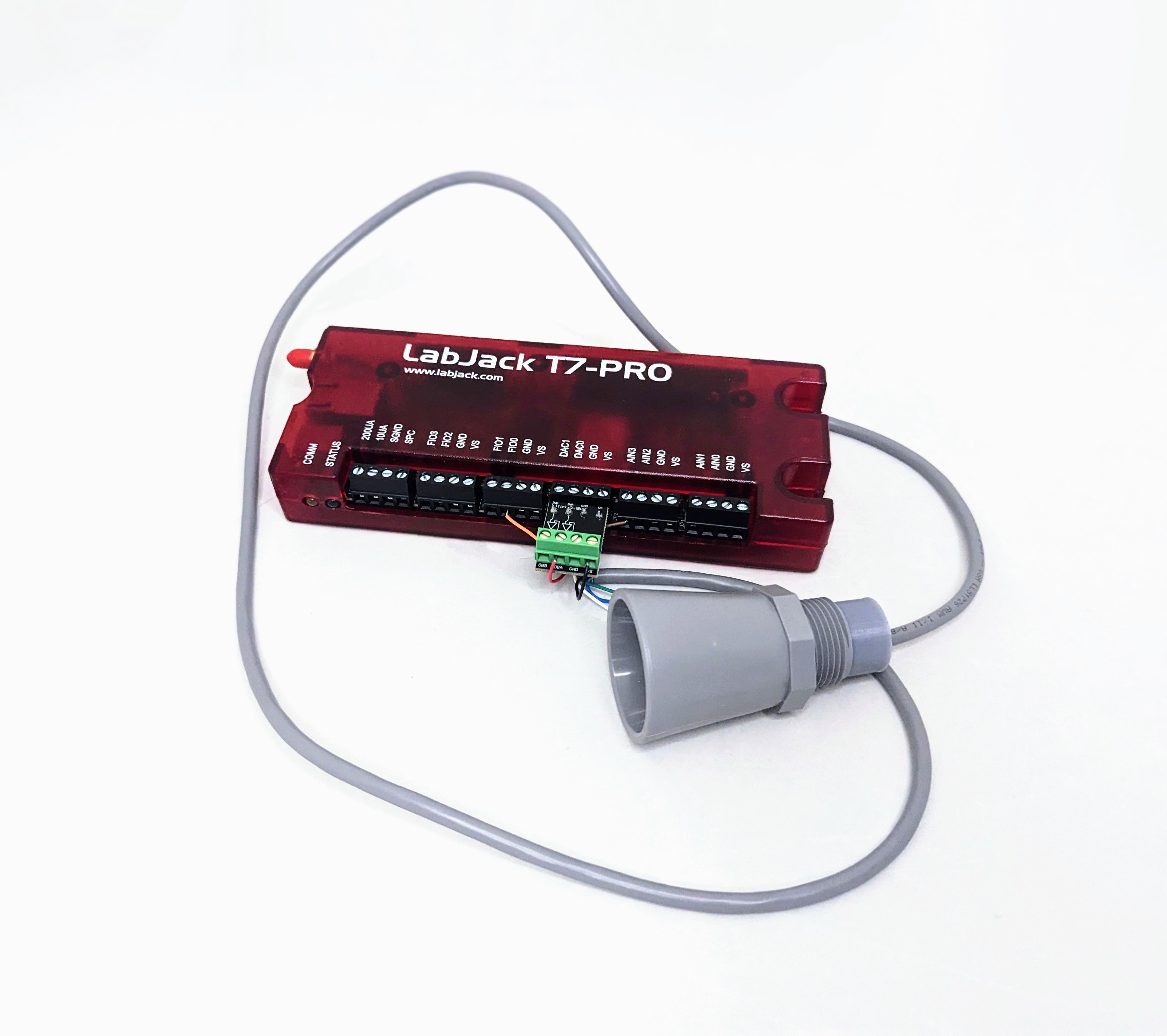
This app note focuses on connecting the sensor to a T7-Pro and using the analog and PWM outputs of this sensor.
Summary
The MB7569 SCXL-MaxSonar-WRM, an ultrasonic sensor made by MaxBotix, measures distances ranging from 300mm to 5000mm. By using high-frequency sound waves, ultrasonic sensors can precisely detect objects by calculating the time of flight for sound to travel from the sensor, bounce off objects, and return. This method provides an accurate distance measurement. The sensor is designed with weather resistance and self-cleaning features, making it ideal for Data Acquisition (DAQ) applications in environments with high moisture levels.

Expected In/Out Values
The sensor has an operating voltage from 2.7V to 5.5V9, and a current draw of ~68mA at 5V.
The analog output ranges 3.2225 V-0.19335 V, with a step size of about 3mV. The PWM outputs a signal width of 0.0003 to 0.005 seconds, at a period of about 2 seconds.
Sensor Connections
To get the sensor properly powered, a LJTick-OutBuff is needed, since Labjack devices can only output a max of 15mA on its own. This should be connected to the DAC1/DAC0 screw terminals.
Connect your sensor to the T7-Pro using the following connections:
Pin 7 -> OBA (on the LJTick-OutBuff)
Pin 6 -> GND
Pin 3 -> AIN3
Pin 2 -> FIO0
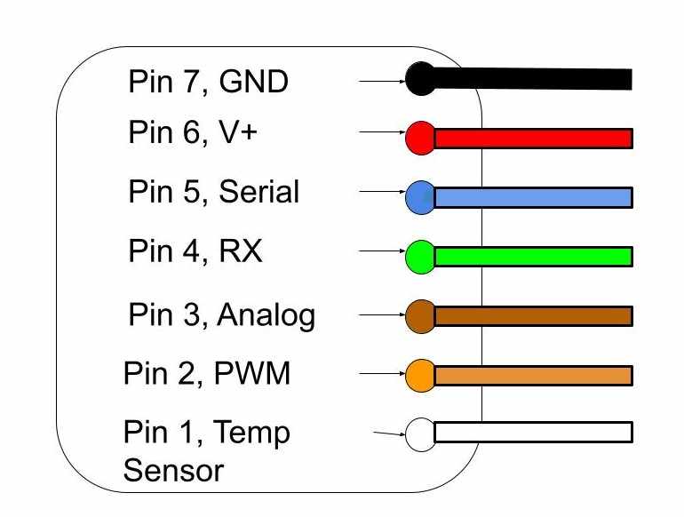
The image below shows the pinouts of the MB7569 sensor, and the respective colored wires from the optional shielded cable you can get for your MB7569 sensor.

Monitoring Sensor Readings Through Kipling
-
Connect your T7/T7-Pro on Kipling. Press the
Analog Outputstab and configure the following settings in this specific order:DAC0 = 3.3 -
Select the
Device Infotab and load LJLogM. -
On LJLogM, set the
# Channelsto 1, and fill row 0 with the following information:Name: AIN3Scaling Equation: y=a*5.120/3.3 -
From here, you will see the live readings of the depth that the sensor reads in meters. When the sensor is moved, it will take about 7 seconds to see the change due to the data being filtered by the sensor.
Taking Depth Readings through Code:
These simple programs can be used with LJM to read your ultrasonic sensor’s PWM and Analog depth readings:
java_maxsonar_sensor_example_code.java (LJM with Java)
python_maxsonar_sensor_example_code.py (LJM with Python)
c++_maxsonar_sensor_example_code.cpp (LJM with C++)
Reducing Analog Noise
The analog output of the sensor has a resolution of +/-5mm. When the analog output is monitored, there are voltage spikes every 1.8 seconds that exceed the resolution. These spikes are caused by the end of the range reading cycle when running the sensor in free run. These spikes and the overall noise of the sensor will increase while using a longer cable for the sensor.
One note on limiting noise is deciding what device to use. This App Note talks about the T7/T7-Pro. However, a T8 will result in higher quality filtered data. On the other hand, The T4’s low-voltage analog inputs (AIN4-AIN11) operate within a 0-2.5V range with a resolution of 0.6 mV, which is too small of a voltage range for the sensor. The high-voltage analog inputs (AIN0-AIN3) have a +/-10V range and a resolution of 5 mV. Although smaller than that of the sensor's, it remains usable.
Another way to reduce noise is by setting resolution index of AIN# terminals. The more you increase resindex, then more filtered data will be obtained; however, it may be relevant to consider resindex's impact on timing for readings.
By incorporating Lua scripts, almost all effects caused by spikes are eliminated nearly completely. These customizable scripts can be used to reduce noise on all your AIN# terminals and save them into User Ram on your T7/T7-Pro:
threshold_average_lua_demo.lua
Using this program, you will be able to compare the different methods of noise reduction and their effects on the sensor’s reading, simply add a jumper between AIN3 an AIN1:
The .vi version of the app above is compatible with LabVIEW versions 7.1 and up:
