An RTD (resistance temperature detector) is a device whose resistance changes with temperature. The two most common variants of RTDs have a sensing element made from platinum and are known as a PT100 (resistance at 0 °C is 100 Ω) and PT1000 (resistance at 0 °C is 1000 Ω.)
General RTD Conversion Equations
There are a few different ways to convert an RTD resistance measurement into temperature. The most straightforward (but most prone to calculation error) is to use a linear fit to convert between resistance and temperature.
PT100 Linear Fit
A PT100 will have a nominal resistance of 100 Ω at 0 °C and the resistance will change by approximately 0.385 Ω/°C. The following linear fit can be found:
TempC = (RRTD - 100) / 0.385
PT1000 Linear Fit
A PT1000 will have a nominal resistance of 1000 Ω at 0 °C and the resistance will change by approximately 3.85 Ω/°C. The following linear fit can be found:
TempC = (RRTD - 1000) / 3.85
More Advanced Conversion Methods
See the following page for some other conversion methods:
If you are using a T-series device, our RTD AIN_EF can be used to handle the RTD resistance to temperature conversion. It uses a rational polynomial to help minimize calculation errors.
RTD Signal Excitation and Wiring
RTDs are measured using the analog input channels (AIN) on LabJack devices. Since the analog inputs on all LabJack devices are configured for voltage measurement, an excitation circuit is required to measure the change in resistance from an RTD. General figures for the two most likely/common measurement circuits are shown below, where RRTD represents the RTD.
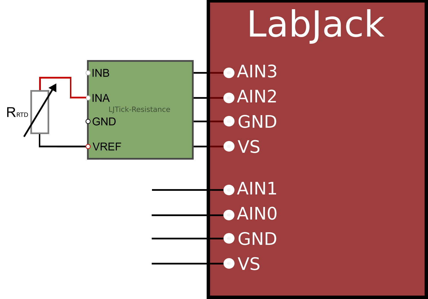
We typically recommend using our LJTick-Resistance-1k to create a resistor divider circuit similar to what is shown in Figure 1 below.
See our Measuring Resistance App Note for other related information. If you have a T-series device, also see our RTD AIN_EF documentation.
The LJTick-Resistance is not recommended for the T8.
The T8 analog channels cannot easily accept the LJTick-Resistance due to their differential configuration and isolation from the power system.
2-wire vs. 3-wire vs. 4-wire
If you have an RTD with 3 or 4 wires, we typically recommend configuring the measurement as if it is a 2-wire RTD. For example, with a 3-wire RTD you would twist together the two wires on one side and connect them as if it were one wire. With a 4-wire RTD you would twist together the two wires on either side of the RTD and connect them as if they were single wires.
The only reason you would not wire a 3-wire or 4-wire RTD like it is a 2-wire RTD is if you need to compensate the wire resistance in your measurements, which should not be required in many situations. See the wire resistance considerations in the error sources section.
Resistor Divider Excitation
A resistor divider circuit can be used to get the RTD resistance in terms of an output voltage change (Vmeas) as shown below. See the Measuring Resistance App Note for additional resistance measurement wiring information.
-
When using the LJTick-Resistance with a T4/T7, you would connect one wire to VREF and the other to one of the IN terminals. Connect the LJTick-Resistance to a screw terminal block with AIN terminals for measurement.
-
If not using the LJTick-Resistance:
-
Connect one wire of the RTD to
Vexc. -
The node at Vmeas+ should be wired to an AIN terminal. For example, connect both one RTD wire and the top wire of your divider resistor to an AIN terminal.
-
The node at Vmeas- should be wired to the appropriate negative terminal on the LabJack. Typically that means LabJack GND, but could mean AIN- for devices with isolated inputs such as the T8. Also connect this negative terminal back to Vexc-.
-

With this configuration, the equation to get the RTD resistance would be as follows:
RRTD = [(Vref - Vmeas) * Rdivider] / Vmeas
From here, you can use the conversion equations above to convert the RTD resistance found to temperature.
For example, if you are using an LJTick-Resistance-1k, the RTD resistance would be found as follows:
RRTD = [(2.5 - Vmeas) * 1000] / Vmeas
Next, lets say you have a PT100 and want to use a linear fit to convert from resistance to temperature. You can sub in RRTD in the linear fit equation to get a final scaling equation as follows:
TempC = [((2.5 - Vmeas) * 1000) / Vmeas - 100] / 0.385
Current Source Excitation
A current source and shunt resistance circuit can be used to get the RTD resistance in terms of an output voltage change (Vmeas) as shown below. See the Measuring Resistance App Note for additional wiring information.
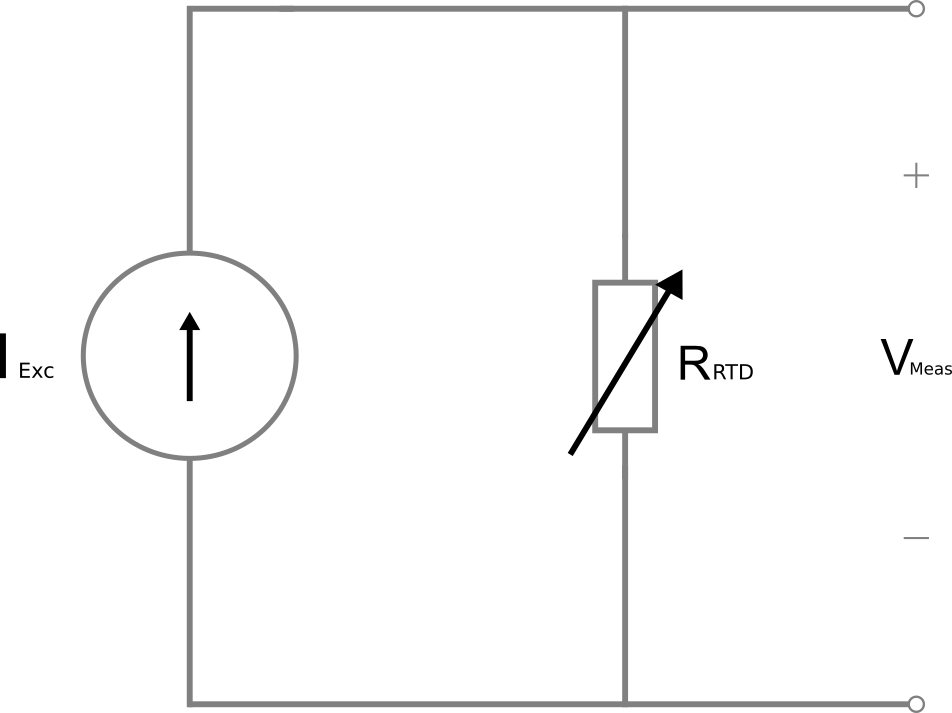
With this configuration, the equation to get the RTD resistance would be as follows:
RRTD = Vmeas/ IExc
From here, you can use the conversion equations above to convert the RTD resistance found to temperature.
For example, if you are using the 200 µA source on a LabJack T7, the RTD resistance would be found as follows:
RRTD = Vmeas/ 0.0002
Next, lets say you have a PT100 and want to use a linear fit to convert from resistance to temperature. You can sub in RRTD in the linear fit equation to get a final scaling equation as follows:
TempC = (Vmeas/ 0.0002 - 100) / 0.385
Troubleshooting
Note that some error may be contributed to the measurement circuit. See the Error Sources section below.
-
If you are seeing higher than expected errors, we recommend starting by removing all external connections to the LabJack and testing the AIN themselves, then if that looks okay compare your signal AIN measurements with a DMM reading. This should help verify that the LabJack and sensor are operating as expected. See our Troubleshooting Your Analog Input Signal App Note.
-
Check your excitation circuit.
-
If using the LJTick-Resistance, measure the voltage between VREF and GND to ensure that it is 2.5V. Connect the input to GND instead of your signal; you should see roughly 0V measurements. The DAC output could be used to simulate an input signal. Set the DAC to a value such as 1 V and verify the actual DAC voltage with a DMM. Pass this signal to the LJTick-Resistance and you should measure a voltage similar to the DAC value.
-
If using a current source excitation such as the built-in 200 µA source on the T7, note that the actual current output may not be calibrated to exactly 200 µA. The expected/calibrated current source value can be read from device flash memory. See your device datasheet for relevant information (U6 / T7).
-
-
Check the output at multiple set points. At room temperature (25°C) a PT1000 resistance should be around 1097.3 Ω. At 0 °C (such as in an ice bath near a chunk of ice) a PT1000 resistance should be around 1000 Ω. If you see some static offset error at both points, you might be able to treat it as an offset in your resistance measurement, like a 2-point calibration. If the resistance measurements look correct but you see some notable error in the temperature reading, there may be some issue with your conversion equation or the setup of the T-series RTD AIN_EF.
Error Sources
There are several possible sources of error in RTD measurements.
Wire Resistance
Wire resistance can cause small errors in the resistance measurement. Equations to approximate the error due to wire resistance are as follows where RTDOhmsPerC is the change in RTD resistance per °C (roughly 0.385 Ω/°C for PT100 and roughly 3.85 Ω/°C for PT1000):
ErrorDegC = WireResistance / RTDOhmsPerC
It is not necessary to account for errors due to wire resistance unless you are working with long wire stretches, and a PT1000 is much more immune to wire resistance errors than a PT100. The following table describes wire lengths that would result in an error of 0.25ºC for PT100 and PT1000 measurements:
|
AWG |
Ω/ft. |
Length for 0.25ºC Error PT100 |
Length for 0.25ºC Error PT1000 |
|---|---|---|---|
|
16 |
0.0040 |
24.0 ft. |
240.0 ft. |
|
18 |
0.0064 |
15.0 ft. |
150.0 ft. |
|
20 |
0.0102 |
9.4 ft. |
94.1 ft. |
|
22 |
0.0161 |
6.0 ft. |
59.6 ft. |
|
24 |
0.0257 |
3.7 ft. |
37.4 ft. |
For example, if you use a PT1000 with 20 gauge lead wires, it would take 94 feet of wire to produce a 0.25ºC error due to wire resistance.
Resistor Divider Excitation Errors
Rdivider assumed value error: Any difference between the actual fixed resistor resistance and expected resistance will show up as error in the measurement:
ErrorDegC = RerrRTD / RTDOhmsPerC
RerrRTD = Rerr
ErrorDegC = Rerr / RTDOhmsPerC
The LJTick-Resistance-1k uses 0.05% resistors (with 10 ppm tempco). This translates to an error in the fixed resistance of ±0.05 Ω, or approximately ±0.13 ºC error when using a PT100.
Vref assumed value error: The reference voltage has a direct relationship to the RTD resistance measurement:
ErrorDegC = RerrRTD / RTDOhmsPerC
RerrRTD≈ VerrVref* (Rdivider + RRTD) / Vref
ErrorDegC ≈ VerrVref* (Rdivider + RRTD) / (Vref* RTDOhmsPerC)
The accuracy of the LJTick-Resistance Vref output is ±0.04% or ±1 mV since it is a 2.5 V output. If using a PT100 where RRTD= 100 (meaning measurement near 0 ºC ) and Rdivider= 1000 for the LJTick-Resistance-1k, the error would be around 0.44 Ω or around ±1.1 ºC error. The error is notably less impactful with a PT1000. If measuring at 0 ºC where RRTD= 1000 and Rdivider= 1000 for the LJTick-Resistance-1k, the error would be around ±0.8 Ω or around ±0.21 ºC error.
AIN accuracy error: There will be an error in the measured voltage due to the analog input accuracy. This would be represented as an error in Vmeas.
RerrRTD= VerrVrefmeas* (Rdivider + RRTD) / Vref
ErrorDegC = VerrVrefmeas* (Rdivider + RRTD) / (Vref* RTDOhmsPerC)
With a U6 or T7, the measurement accuracy at ±10V input range is ±2 mV. If using a PT1000 where RRTD= 1000 (meaning measurement near 0 ºC ) and Rdivider= 1000, Vref = 2.5 for the LJTick-Resistance-1k, the error would be around ±1.6 Ω or around ±0.42 ºC error.
Vref feedback measurement error: Taking a measurement of Vref with an AIN could be done to potentially reduce error from the assumed Vref value. However, there is an error in the feedback measurement to consider. It would be an AIN measurement error, so see the equations and example in the AIN accuracy error section above. You may note that the feedback error when using an LJTick-Resistance is greater than the error seen if the assumed value of Vref is used, so you are actually better off not doing a feedback measurement of Vref when using the LJTick-Resistance-1k.
Current Source Excitation Errors
Iexc assumed value error: Any deviation between the expected and actual excitation source current will show up as an error in the measurement:
ErrorDegC = RerrRTD / RTDOhmsPerC
RerrRTD = Ierr * RRTD / I
ErrorDegC = Ierr * RRTD/ (RTDOhmsPerC * I)
The 200 µA source on the U6/T7 has an accuracy of ±0.2%, or ±400 nA. If using a PT100 near 0 ºC where RRTD= 100, this would correspond to an error in the calculated RTD resistance of around ±0.2 Ω or around 0.52 ºC error. If using a PT1000 near 0 ºC where RRTD= 1000, this would correspond to an error in the calculated RTD resistance of around ±2 Ω or around 0.52 ºC error.
AIN accuracy error: There will be an error in the measured voltage due to the analog input accuracy. This would show up as an error in Vmeas.
ErrorDegC = RerrRTD / RTDOhmsPerC
RerrRTD = Verrmeas / I
ErrorDegC = Verrmeas/ (RTDOhmsPerC * I)
The impact of this error will depend on some device settings. Particularly, note that the AIN accuracy specification for devices with built-in amplification increases as gain increases.
With a U6 or T7, the measurement accuracy at ±10V input range is ±2 mV. If using a PT100 where RRTD= 100 (meaning measurement near 0 ºC ) and the 200 µA source such that I = 0.0002, the error would be around 10 Ω or about ±26 ºC error. However, a higher gain setting of x100 (±0.1V) could be used since the measured voltage would only be around 0.02V. The accuracy spec at ±0.1V setting is ±20 µV, and the error would correspond to around ±0.1 Ω or ±0.26 ºC error.
Other 200 µA and 10 µA source considerations: See the remarks in the 200 µA and 10 µA T-series documentation.
Accounting for Wire Resistance with a 3-Wire RTD and LJTick-Resistance
You could use the 3rd wire on your RTD and take differential measurements to help account for wire resistances, but it often adds more complications than are justifiable. There are two quick solutions to help compensate for wire resistance:
-
If you know that the extra resistance is causing an 'X' ºC error we would suggest you simply adjust by 'X' ºC in software.
-
Use thicker wire to decrease the resistance of the wires, and therefore decrease the associated error.
If you want to use the third wire, the resistance of each length of wire (Rw) plus the RTD resistance (RRTD) is the following:
2Rw + RRTD
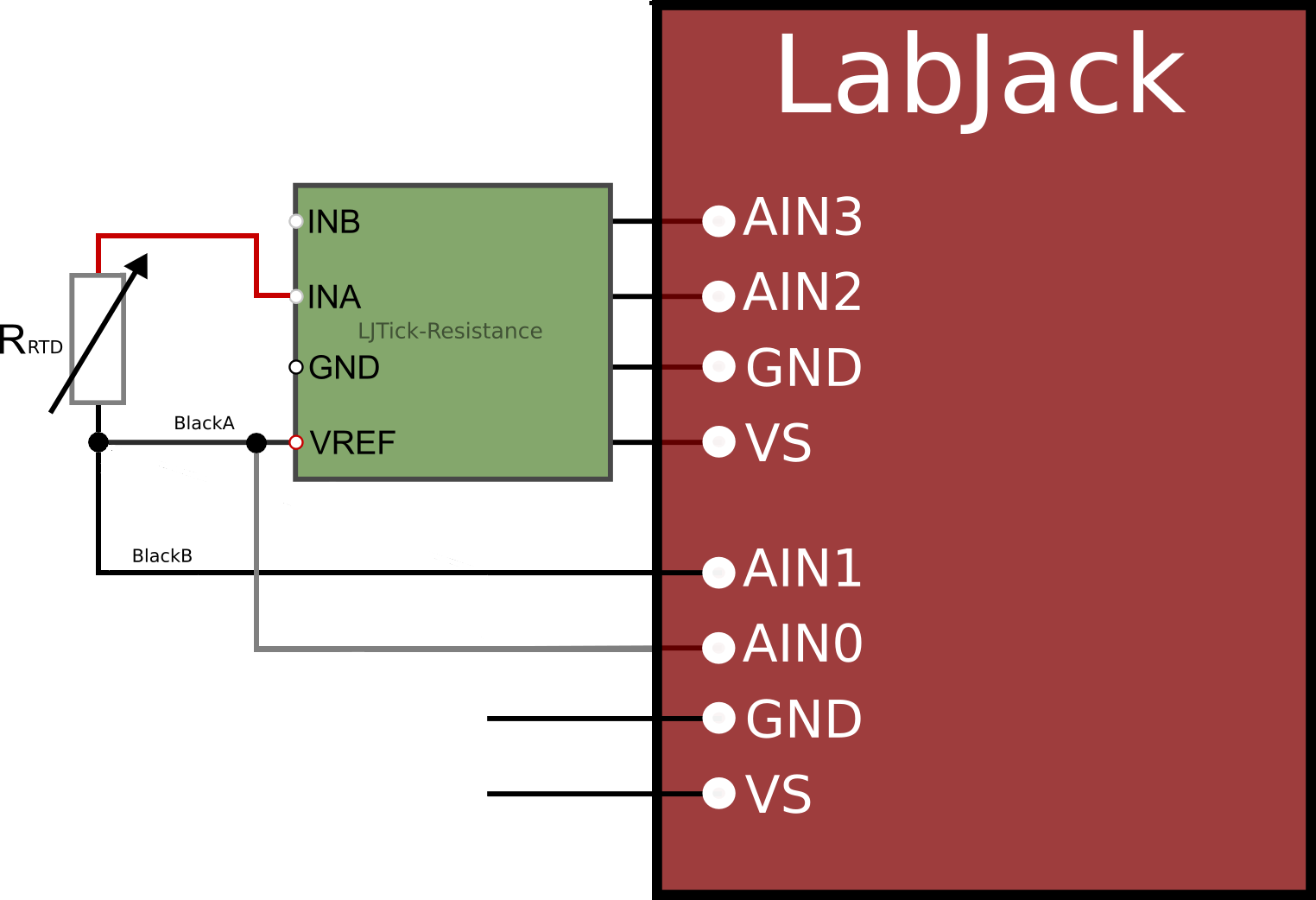
Say your sensor has one red wire and two black wires (BlackA and BlackB). Presumably the two black wires connect to one side of the RTD and the one red wire connects to the other side of the RTD. Connect as follows:
-
RTD-BlackA connected to LJTick-Resistance Vref, and also a small jumper from LJTick-Resistance Vref to AIN0.
-
RTD-BlackB connected to AIN1.
-
RTD-Red connected to LJTick-Resistance VINA which goes to AIN2.
A single-ended measurement of AIN2 (Vmeas) gives you the voltage across the fixed resistor in the LJTick-Resistance (Rdivider):
I = Vmeas / Rdivider
The differential measurement between AIN0 and AIN1 (Vain01) is the voltage across one Rw, so you can determine Rw:
Rw = Vain01 / I
Rw = Rdivider * Vain01 / Vmeas
The voltage across the RTD and wire (2Rw + RRTD) is Vref minus Vmeas. The current found above can be used to solve the system of equations for RRTD while accounting for the wire resistance. Again, Vmeas is the single-ended measurement of AIN2 in this example:
2Rw + RRTD= (Vref- Vmeas) / I
2Rw + RRTD= (Vref- Vmeas) *Rdivider /Vmeas
2Rdivider * Vain01 / Vmeas + RRTD= (Vref- Vmeas) *Rdivider /Vmeas
RRTD= (Vref- Vmeas-2Vain01) *Rdivider /Vmeas