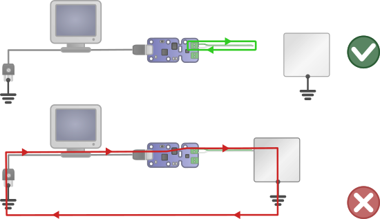
Ground Loops
This is a common and complex problem people encounter when using thermocouples. It occurs when bare thermocouple wire is used, or a metal thermocouple probe where one of the thermocouple wires inside is connected to the probe (often called a "grounded" probe). If multiple of these are connected to a common conductor (e.g. a system of connected metal pipes), and connected single-ended to the LabJack, you can get ground loops and unexpected thermocouple junctions.
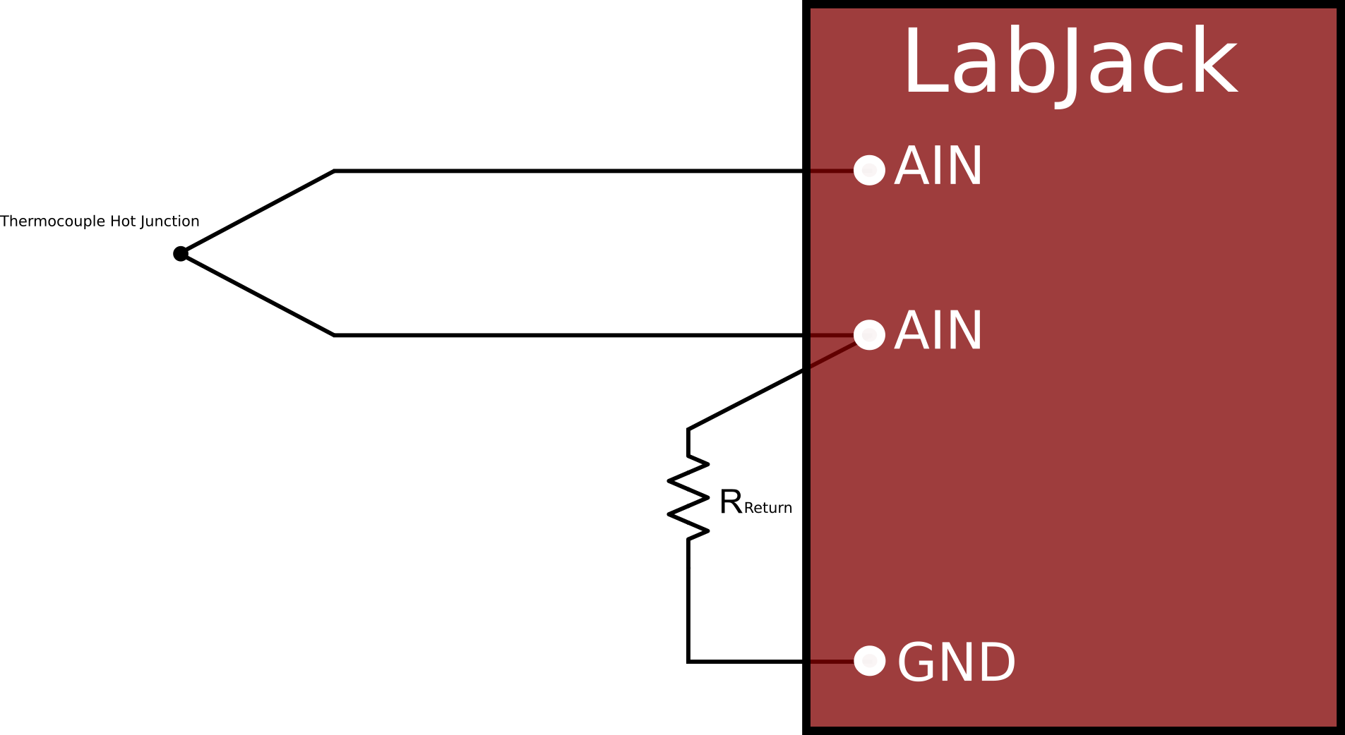
The typical fix is to use differential inputs with a resistor (100k is typical) from the negative input to GND. As noted in the Differential Readings Application Note, the resistor is sized to be low enough to provide a path for bias currents but high enough to prevent ground loop issues. Differential connections usually prevent this problem, but sometimes further steps are needed (e.g. channel-to-channel isolation).
To prevent this, install thermocouples so that this situation cannot occur:
a. Use some sort of substance, between the thermocouple metal and test specimen, that has good thermal conduction but poor electrical conduction. Epoxy, tape, etc.
b. Place the thermocouple near, but not actually touching, the test specimen.
c. Use probes that are called "ungrounded". A very common option.
d. Use thermocouples with an electrically insulating layer between the thermocouple metal and test specimen. One example is the SA1 series of self-adhesive thermocouples from DwyerOmega.
Too much noise
If you see too much noise (notable swings) in your readings, try the following:
Range and Resolution configuration settings:
The most common problem leading to too much noise is not having the correct range and resolution settings (on the T7/U6 in particular). To test:
-
Disconnect the thermocouple and jumper the analog input to GND (or both analog inputs to GND if using a differential input).
-
For T-Series (T4, T7/T7-Pro, T8): Open Kipling and go to the Analog Inputs tab.
For UD-Series (U3-LV/U3-HV, U6/U6-Pro, UE9/UE9-Pro): Open LJ Control Panel and go to the Test Panel window. -
Set the range and resolution as needed and look at the noise level on the applicable channels and compare to the specified typical noise for the LabJack. See the specifications in the appropriate device datasheet(s):
-
Appendix B of the LJTick-InAmp Datasheet
With the default thermocouple settings of Range=0.1 and Resolution Index=0, the noise level of a T7/U6 will be perhaps 1 or 2 microvolts. After confirming the proper noise level in Kipling/LJControlPanel, go to your actual software and look at the raw voltage to confirm the proper noise level there.
Floating Differential Input:
If using a differential input you need a resistor from the negative channel to GND. See the Differential Readings App Note.
Removing Environmental Factors:
See the Bad ground loops, ground offsets, and EMI susceptibility complications described above.
-
Try removing all external connections from the LabJack except one thermocouple and testing. This will help ensure that external connections are not affecting the reading.
-
If your thermocouple is mounted to an electrically conductive surface, try a test measurement with a thermocouple that is not mounted (in free air). This could help if there is an issue with a ground loop from your mounting.
-
If possible, try testing with the LabJack and thermocouple in a different environment. This can help establish whether something in your test location is causing the issue.
Wrong temperature
If the issue appears to be a static error, for example regularly reading 5 above the expected temperature, there is typically a problem with either:
-
the CJC setup
-
the thermocouple hardware setup
-
an issue with the conversion math
Is the CJC temperature correct?
See the Cold Junction Compensation section in “How Does a Thermocouple Work?”
If using the AIN_EF feature on a supported T-series device, read AIN#_EF_READ_C for the CJC temperature.
If there is a +10 degree error in the measurement of the cold junction, you will see a roughly +10 degree error in the calculated value for absolute temperature of the remote end of the thermocouple.
-
If there appears to be a static error, you may be able to simply add an offset to your CJC temperature reading to account for it.
-
If doing CJC, note that the internal temperature sensors on LabJack devices sometimes do not properly reflect the cold junction temperature, and an external CJC temperature sensor such as an LM34 may be useful. For example, when using an expansion board such as the CB37, the cold junction may be at room temperature whereas the LabJack internal temperature sensor is a few degrees warmer than room temperature due to self heating from the LabJack. These errors in the cold junction temperature reading may be worse in environments with a significant temperature gradient.
Is the raw thermocouple voltage as expected?
If using the AIN_EF feature on a supported T-series device, read AIN#_EF_READ_B for the raw thermocouple voltage.
Test against a 0 V condition: Bring the remote end (hot junction) of the thermocouple near the local end (cold junction) to check the condition where both ends are at the same temperature. You should read very close to 0 volts, within a few hundred microvolts typically. A thermocouple gives you a voltage related to the difference in temperature between the 2 ends, so if the cold junction and hot junction are at the same temperature, the voltage difference measured should be close to 0. This is a good way to test the thermocouple setup if you are uncertain about the cold junction and/or hot junction temperatures.
Test any arbitrary temperature: To check at some arbitrary temperature difference, see the NIST tables linked in the thermocouple basics section above. For example, say you have a Type K thermocouple where the cold junction is at an expected temperature of 25 °C and hot junction at 35 °C:
NIST Table of Thermoelectric Voltages and Coefficients
The voltage at the 25 °C end is 1.000 mV and the voltage at the 35 °C end is 1.407 mV, so the difference is 407 µV. If the LabJack is reporting 407 µV, then continue to step 3. If not, use a DMM to measure across the screw-terminals where the +/- leads are connected to see if the DMM reading is different or agrees with the LabJack.
If the DMM does not agree:
-
There may be a ground offset issue (see the complications section above).
-
If you are taking a differential measurement, ensure that you have a reference to GND (see the connections section above).
-
If using a differential connection, there could perhaps be an issue with common mode voltages; check the voltage on each AIN input compared to GND. Both should be near 0 and within the typical measurement range of your device.
Is the math correct?
If the CJC temperature is right and the raw thermocouple voltage is right, then there may be something wrong with the conversion math. Note that our conversion functions typically only support the ranges (and associated reverse coefficient polynomials) described on the NIST website for conversion.
LJTick-InAmp Troubleshooting
Check that the LJTick-InAmp offset is correct and that the noise level is as expected.
With signals connected to the LJTIA, a DMM can be used to measure the differential input INA+ versus INA-, and also measure the output (versus GND), and confirm that you see Vout = (gain*Vdiff) + offset.