The following guide is intended to expand upon our basic timer configuration tutorial as well as describe a useful timer and counter setup to test PWM and/or timer input capture features.
1. Get familiar with basic timer and counter setup in LJControlPanel.
See our tutorial for configuring counters in LJControlPanel. Then, see our tutorial for configuring timers in LJControlPanel.
2. Open your device in LJControlPanel, open the Test panel, then navigate to the timer/counter configuration window.
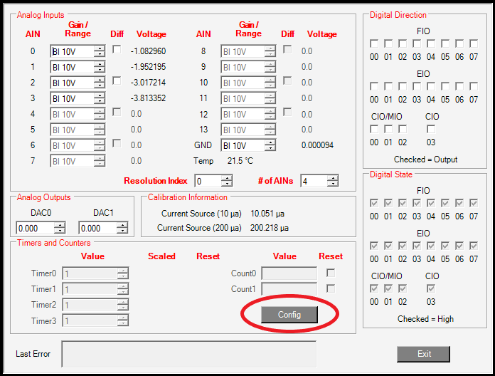
3. Enable two timers and Counter0.
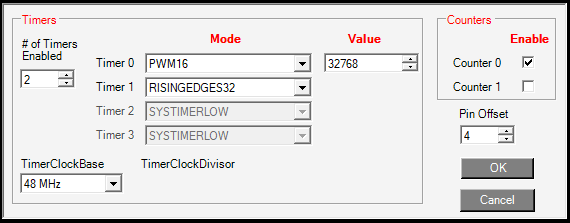
Set the Timer0 Mode selection to PWM16 and Timer1 Mode selection to RISINGEDGES32.
Leave the TimerClockBase"as the default 48 MHz clock. This will result in a PWM frequency of ~732Hz. The Timer0 Value entry determines the PWM low time and therefore the duty cycle when using the PWM16 feature. The default value of 32768 will produce a 50% duty cycle. See the PWM16 feature documentation for more information.
Click the Enable box for Counter0 and set the Pin Offset entry to 4. This configuration will result in a PWM output (Timer0) on FIO4, Period measurement (Timer1) on FIO5, and Counter0 on FIO6. This configuration is most convenient for U3 users; U6 or UE9 users could apply a pin offset of 0 to put Timer0 on FIO0, Timer1 on FIO1, and Counter0 on FIO2. The following steps assume a pin offset of 4 is used.
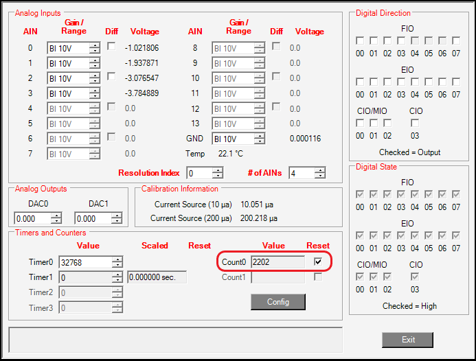
4. Connect a wire between the Timer0 and Counter0 DIO.
Select OK in the timer/counter configuration window to apply your changes. When you connect Timer0 (FIO4) to Counter0 (FIO6) you should see the Value section of Counter0 increasing if the PWM is set up correctly. LJControlPanel updates values approximately 1 time per second, so a PWM set up with a frequency of 732Hz should result in the Counter0 value incrementing approximately 732 counts each update.
If you do not see the proper count increment, ensure your wire is firmly screwed down into the Timer0 and Counter0 terminals and otherwise check your timer/counter configurations for errors.
5. Move or add a wire to connect the Timer0 and Timer1 DIO.
The previous step should verify the operation of the PWM output feature. A wire could then be connected between Timer0 (FIO4) and Timer1 (FIO5) so that you can verify the operation of the input period measurement feature set up on Timer1. If desired, the wire between Timer0 and Counter0 can be maintained to test both the PWM and the period measurement feature at once.
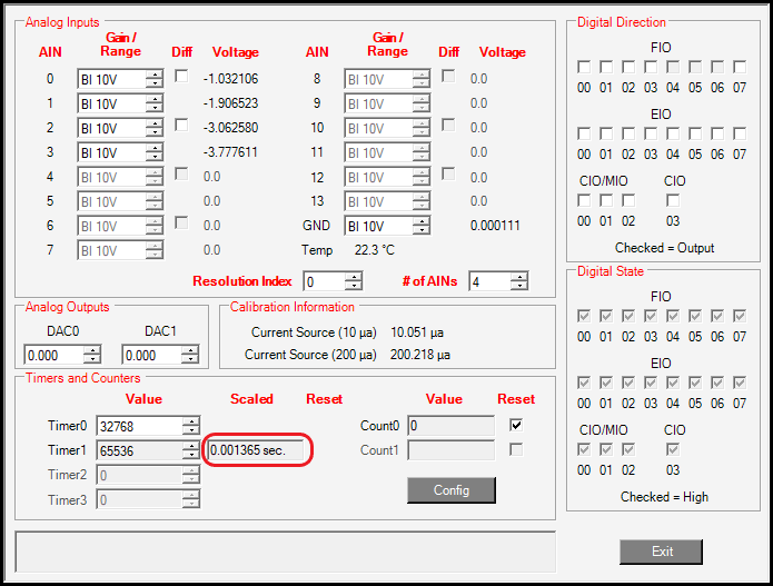
With a wire attached between Timer0 (FIO4) and Timer1 (FIO5), you should see the Scaled value next to Timer1 reading out approximately 1/732 (0.001366) seconds if it is properly tracking the 732Hz PWM.
The Timer1 Value entry should always read exactly 65536 during this test since Timer0 and Timer1 use the same clock; a rising edge occurs exactly every 65536 clock cycles when Using PWM16 and the period measurement feature Value entry is the number of clock cycles measured between rising edges.
If you do not see the proper values, ensure your wire is firmly screwed down into the Timer0 and Timer1 terminals and otherwise check your timer/counter configurations for errors.
Also note that the timers have an edge rate limit of approximately 30,000 edges/s, so we do not expect input capture features such as period measurement to properly capture PWM or other signals with frequencies higher than 30,000Hz. See the timer operation performance notes.
6. Troubleshooting a Period Measurement Input.
See the troubleshooting guidance in step 8 of our basic Timer Configuration tutorial.
If the measured period is too short, this suggests extra edges are being detected. If the signal is very noisy it can cause multiple fast edges rather than a single edge. A simple low pass RC filter (e.g. R=1k and C=0.01uF gives a cutoff frequency of 16kHz) is a possible solution, but the problem suggests the signal is very noisy and could be a symptom of improper connection. Mechanical switch signals can be susceptible to signal bounce, which can result in additional edges; see the guidance in our Switch Signal app note.
If the measured period is too long or returning 0, this suggests that edges are not being detected. This often means the signal is not switching between logic low (values less than 0.8V) and logic high (values greater than 2.0V) or the signal frequency may exceed the edge rate limits of the timer. See the timer operation performance notes.
Next Step
See step 9. in our Timer configuration tutorial to save timer/counter configurations and afterwards you can move on to Logging Timers/Counters.