Timer features on UD devices can easily be configured and read without custom software by using our LJControlPanel and LJLogUD/LJStreamUD software on Windows.
1. Configure a counter.
If you are using an input timer feature (period measurement, etc.) we recommend you first configure a counter and get it to increment properly before attempting to configure a timer.
2. Open the device in LJControlPanel.
Follow steps 1-6 in our U3/U6/UE9 Quickstart Tutorials.
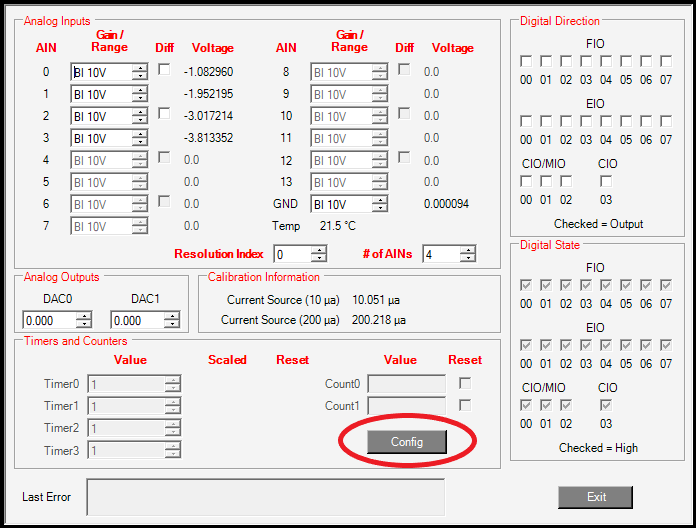
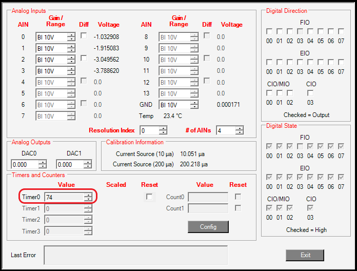
3. Click the Config button in the Timer/Counter section of the Test panel.
Once pressed a new window should appear with more timer and counter settings.
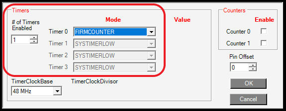
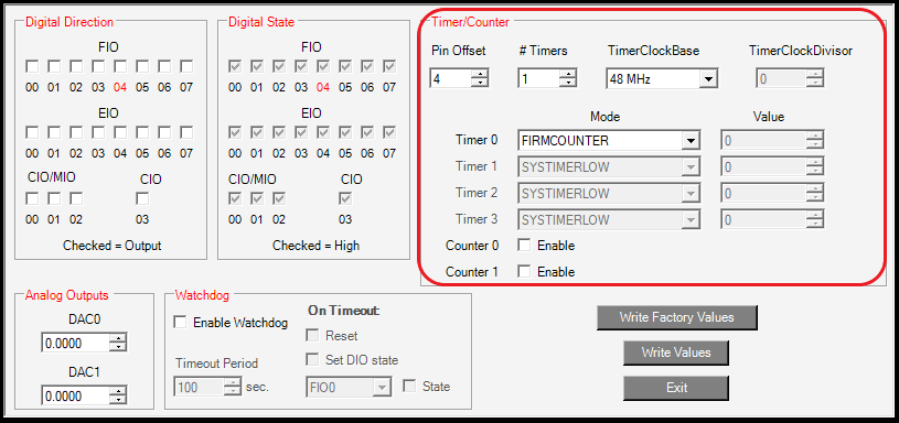
4. Enable your timers.
For this tutorial, we will set up a firmware counter on Timer0, but note that there are several other timer options available. See the timer/counter datasheet page of your respective device for more information: U3/U6/UE9.
Set # of Timers Enabled to 1 and change the mode of Timer0 to FIRMCOUNTER.
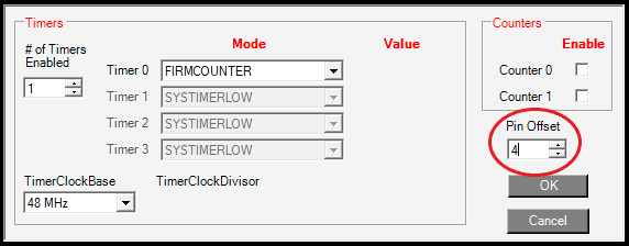
5. Set the Pin Offset.
Set the Pin Offset entry to 4 to put Timer0 on FIO4. This is most convenient for U3 users; U6 or UE9 users use a pin offset of 0 to put Timer0 on FIO0 (FIO4 on the U6 & UE9 is only available through the DB37 connector).
Note: The minimum pin offset for the U3 is 4. See the timer datasheet page linked in step 3 for more information.
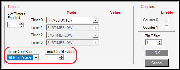
6. [Optional] Change the timer clock frequency and divisor.
Selecting a clock base with a divisor will automatically pop up a window for modifying the TimerClockDivisor as shown below.
7. Click "OK".
The smaller timer/counter window should close and you should now see your timer value incrementing if you have a good pulse input attached to the timer DIO pin. If you are unsure if you have a good pulse input, a jumper wire clamped in a GND terminal should produce increments when you tap the other end of the wire to the inside-back of the timer/counter DIO pin terminal [1].
8. Troubleshooting an input signal.
With a typical digital signal source, you would connect signal+ to a capture timer DIO (FIO4 for U3, FIO0 for U6/UE9 in this tutorial) and connect signal- to a GND terminal on the LabJack.
The necessary connections for your signal could depend on the details of your signal. Some further resources that may be useful for troubleshooting a digital signal are the Driven Signals and Open-Collector Signals app notes.
Always ensure you have a good electrical connection from your signal to the LabJack. Touching a conductor to the top of the screw head of an un-clamped screw terminal is rarely a valid electrical connection. The screw head is usually a valid connection point when the terminal is clamped, but the only guaranteed valid connection is to securely clamp a conductor/ signal wire inside the screw terminal.
If your signal is not giving you good measurements, use a DMM or oscilloscope to confirm you have valid voltages on the DIO line. The digital input set up in this tutorial is looking for a rising edge, which means that the state of the digital input changes from low to high. On UD devices a low is less than 0.8V and a high is greater than 2.00V. See the specifications in your device datasheet for further details U3/U6/UE9.
9. [Optional] Advanced testing.
For more advanced testing of other features, such as frequency input and PWM output, multiple timers, and counters could be configured.
See our Advanced Timer/Counter Testing tutorial.
10. [Optional] Save your timers and counters in your startup configuration.
This is suggested if using LJLogUD, LJStreamUD, or other simple polling programs, but not needed if your software will do the configuration. Also note that U3 hardware revisions 1.20 and 1.21 do not support timer/counter startup configurations.The U3-LV and U3-HV are hardware revision 1.30.
To save your timers and counters for startup you must set up the timers/counters in the Config Defaults panel of LJControlPanel rather than the Test panel.
-
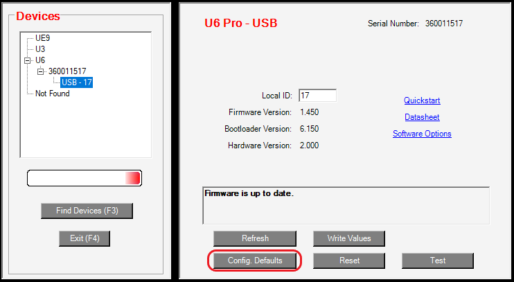
First close the Test panel and click
Config Defaults.
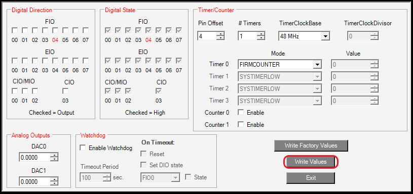
Set up all of your timer/counter settings.
Click Write Values. A new window will pop up; Click Yes to save your configuration.
Close LJControlPanel and power cycle the device to apply your changes. Note that the Test panel will not load your configurations, so we recommend you test the feature in LJLogUD. You can also return to the Config Defaults screen in LJControlPanel to see if it shows the power up defaults you set.
Notes
[1] LabJack digital inputs have an internal 100k pull-up that weakly holds them high, so when you connect a GND wire to a digital input, it will pull the line low and create a falling edge. When you pull out the wire you get a rising edge. You are not likely to make a perfectly clean single contact, so a counter will typically increment many counts each time you tap the wire. Also note that you should touch the ground wire to the inside-back of the counter terminal.
Next Step
Once you are all set up with your timers and counters you can move on to Logging Timers/Counters.