Introduction
Rotary encoders convert angular position into a digital or analog signal. That signal can be used to monitor how far and in what direction a shaft has rotated. There are two general classifications of encoders, absolute and incremental encoders.
Absolute Encoders
An absolute encoder will produce a unique code for each shaft position that it can resolve. The advantage is that the position can be checked when an application would like to know position and does not need to be continuously monitored. The disadvantage is that resolution is usually less and reading the code usually requires more complicated interface systems.
Absolute encoders utilize a variety of interface configurations. Options range from serial protocols to parallel interfaces. The wide range of configurations requires that each encoder be approached on a case by case basis.
The remainder of this app-note will focus on incremental encoders.
Incremental Encoders
Incremental encoders allow position to be determined relative to a starting point. That starting point can be the position when the tracking system was started, a z-phase reset pulse, or any time the LabJack device is instructed to reset its tracking.
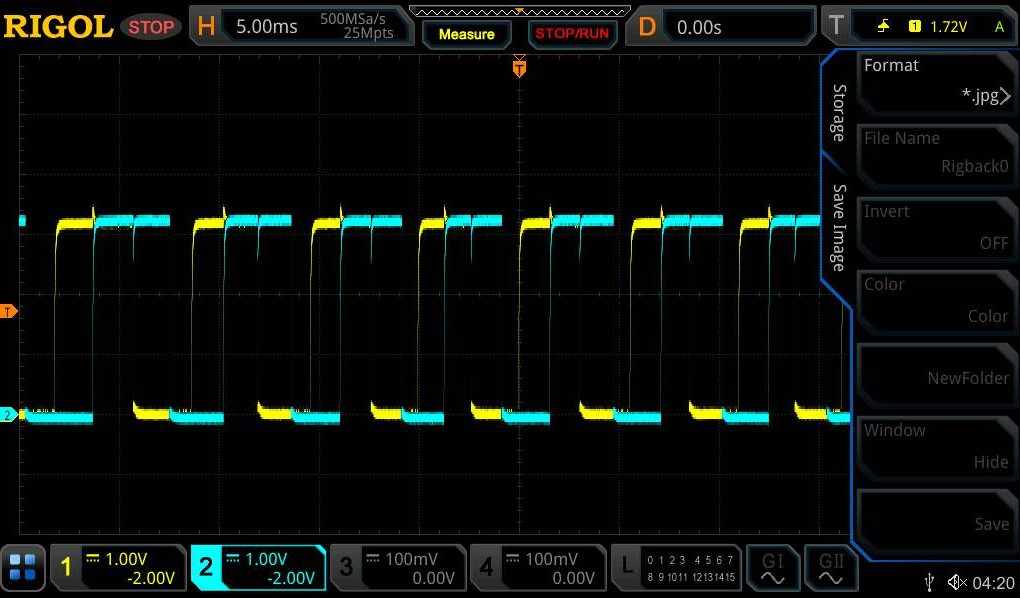
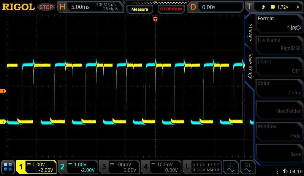
Incremental encoders typically output data in the form of two digital signals to indicate both position and direction of rotation, this digital waveform looks like two square waves that are 90 degrees out of phase as can be seen in the figures below. Incremental encoders that output these signals are often referred to as quadrature encoders.


Prerequisites
We need to select both a LabJack DAQ device and an encoder.
LabJack Device Selection
All T-series devices are capable of monitoring quadrature signals. Each device has a limit to the number of quadrature pairs that can be monitored and a limit to the maximum pulse rate which can be processed.
-
See here for device and pin compatibility: https://support.labjack.com/docs/13-2-11-quadrature-in-t-series-datasheet
-
See the “Rate Limits” section below for maximum rates.
Rate Limits (Edges/s, edges per second)
LabJack devices have a limit to the number of pulses per second that they can process. We define that limit as Edges per second. Each pulse will produce a rising edge and a falling edge. And each encoder has two lines sending those pulses. If both lines are outputting 100 Hz, that is 200 edges per second per line, or 400 edges per second total. For specific device limits, see the specifications in A2-2.
Encoders
Encoders should be selected which provide the required resolution without generating more pulses than the LabJack can process. We can determine how many edges per second an encoder will produce by multiplying the pulses per revolution by the expected rotation rate, then multiplying by four.
Ex: 500 RPM, 4096 pulses per revolution (ppr). Total edges per second = 4 * 4096 * 500RPM / 60 = 136533 edges per second. This more more than LabJack devices can handle (see “Rate Limits” above). We can fixe this by using an encoder with fewer ppr. Switching to an encoder with 512 ppr produce total edges per second of 4 * 512 * 500RPM / 60 = 17067 edges/s.
Z-Phase
Some encoders have a z-phase line. The z-phase line will reset the position tracking when the encoder reaches a specific point.
Encoder recommendations
Most qaudrature encoders will work LabJack DAQ devices. This app-note was tested with a H38S100B.
Wiring an Encoder with a T-Series LabJack
Most encoders have at least four connections:
-
Channel A - The first of the two signals used to indicate changes in the encoders position.
-
Channel B - The second of the two signals used to indicate changes in the encoders position.
-
VCC - The positive power supply connection.
-
GND - The negative power supply connection.
Additionally, some encoders will have:
-
Channel Z - This line will indicate when the encoder is is in the reset position.
-
Channel A' - A prime, also known as NOT A, will always output the opposite of Channel A. This line is not used when connecting to a LabJack DAQ.
-
Channel B' - B prime, also known as NOT B, will always output the opposite of Channel B. This line is not used when connecting to a LabJack DAQ.
The two phases must be plugged into two quadrature enabled I/O lines. See here for valid pairs: https://support.labjack.com/docs/13-2-11-quadrature-in-t-series-datasheet
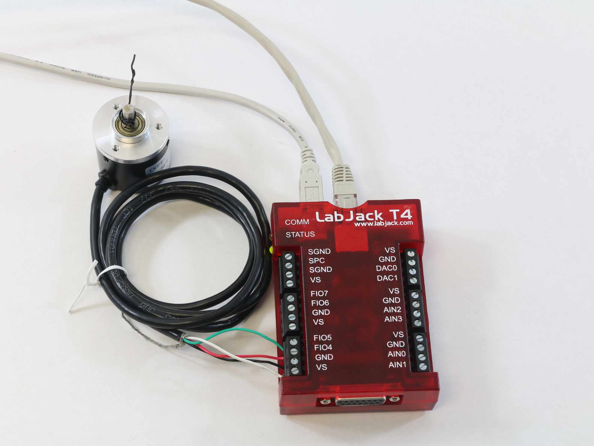
The even I/O line should be connected to phase A and the odd I/O line should be connected to phase B. For example, when using a T7, the phase A can be connected to FIO0 and phase B connected to FIO1. When using a T4, phase A can be connected to FIO4 and phase B connected to FIO5, as shown in the figure below. Any VCC and ground on the T-Series device will be sufficient for the other signals.

Sometimes, a quadrature encoder will also have an optional Z phase which sends a pulse after each full rotation. T-Series devices are capable of enabling an I/O line to receive this Z phase as a reset so the encoder only keeps track of the position relative to a single rotation. For more information on the quadrature in functionality of the T-Series see Quadrature In.
To test the functionality of a quadrature encoder after wiring, the VCC and GND signals can be connected on a T-Series device and the two phases can be monitored on different channels of a scope. When the encoder is moved, the two expected out of phase waves should be visible on the scope as seen below.


LJM Library Psuedocode
Data from Quadrature Encoders can be read from T-Series devices on multiple platform types (Windows, Mac, Linux, and single board computers) by using the LJM library and starting with our published example code. If the device's Ethernet or WiFi connection types are used, larger SCADA systems or Modbus Client Applications that implement the Modbus TCP protocol can also be used. There are also a few 3rd party applications capable of communicating with LabJacks.
Configuration of a T-Series Device
The Quadrature Input section of the T-Series datasheet shows an example of configuring a device's DIO6 and DIO7 I/O lines in the example section. Below are the registers that need to be written to configure the device to use DIO0/DIO1 (aka FIO0/FIO1):
Setup Quadrature Input DIO_EF - c
-
LJM_eWriteName(handle, "DIO0_EF_ENABLE", 0); //Make sure DIO-EF is disabled on DIO0
-
LJM_eWriteName(handle, "DIO1_EF_ENABLE", 0); //Make sure DIO-EF is disabled on DIO1
-
LJM_eWriteName(handle, "DIO0_EF_INDEX", 10); //Set feature index for DIO0 to quadrature.
-
LJM_eWriteName(handle, "DIO1_EF_INDEX", 10); //Set feature index for DIO1 to quadrature.
-
LJM_eWriteName(handle, "DIO0_EF_ENABLE", 1); //Enable quadrature DIO-EF on DIO0, for A phase.
-
LJM_eWriteName(handle, "DIO1_EF_ENABLE", 1); //Enable quadrature DIO-EF on DIO1, for B phase.
For register descriptions see the datasheet section: 13.2.11 Quadrature Input - Configure
Reading Data
Once configured, the LabJack DAQ will continuously track the change of position. An application can read read the current position by reading the DIO#_EF_READ_A register. During any read, the count can be reset by reading from the DIO#_EF_READ_A_AND_RESETregister. Detailed information about the registers that can be read is found in the quadrature section of the datasheet.
-
// Read the quadrature input's current count and don't reset the count back to zero
LJM_eReadName(handle, "DIO0_EF_READ_A"); -
// Read the quadrature input's current count and re-set the count back to zero
LJM_eReadName(handle, "DIO0_EF_READ_A_AND_RESET");
For register descriptions see the datasheet section: 13.2.11 Quadrature Input - Read
Interpreting the values
Another option is to use the READ_A_F register. When reading the _F variant, firmware will covert the value into a 32-bit IEEE754 float. The value from the float does not need to go through the twos complement conversion.
The value returned from READ_A is a 2’s complement number. Conversion to a signed integer will need to be done in the application layer.
https://en.wikipedia.org/wiki/Two%27s_complement
Calculating Rotation Angle
The change in angle from the initial position or the last reset can be calculated as follows:
encoderCountsPerRevolution = 400 // This is a property of the selected encoder.
// Read the quadrature input's current count and don't reset the count back to zero
rawValInCounts = LJM_eReadName(handle, "DIO0_EF_READ_A");
relativeLocationInCounts = twos complement(rawValInCounts) // Typically looks like (-1 * (~rawValInCounts + 1)), "~" is the bitwise not operator.
// Calculate Number of Revolutions
numRevolutions = relativeLocationInCounts / encoderCountsPerRevolution
// Convert counts to degrees
degreesFromZero = relativeLocationInCounts % encoderCountsPerRevolution * 360 / encoderCountsPerRevolution
Checking for Errors
Each edge produced by an encoder must be observed and processed by the LabJack. If edges occur too quickly, one or more may be missed. The missed edges will be detected as an invalid quadrature sequence. Any time this happens, one or more counts will be missed. The number of invalid sequences that have been detected is reported in the DIO#_EF_READ_Bregister.
-
// Read the quadrature input's current count and don't reset the count back to zero
LJM_eReadName(handle, "DIO0_EF_READ_B");
See the troubleshooting section below if errors are being detected.
Stream Mode
The quadrature position can be read more quickly by reading through stream mode. See this communication section for information about command-response and stream mode. See the Reading with LJStreamM section below for more details.
Testing with Kipling
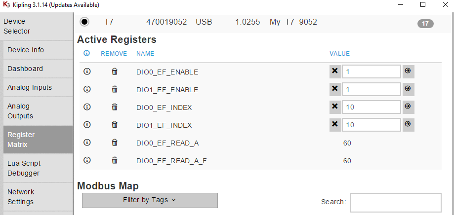
The fastest and easiest way to test the hardware setup and configure the DAQ device is to use Kipling’s register matrix. Within the register matrix, add the six registers discussed in “Configuration of a T-Series Device” above. Note that the 0s and 1s can be replaced by the lines your encoder is connected to. Just be sure that those lines support quadrature as discussed in “LabJack Device Selection” above.
With the six registers in added, follow these steps to configure:
-
Write both of the ENABLE registers to 0 (zero). This will clear any previous settings on those lines.
-
Set both INDEX registers to 10. 10 is the feature index defined on the quadrature datasheet page.
-
Write both of the ENABLE registers to 1.
The T-Series DAQ system will now be tracking the encoder and the result will be displayed next to the READ registers. Rotate the encoder a few times in each direction. Notice that the _A_F register will go negative, while the _A register will only show positive numbers. The values in _A are 2’s compliment, but Kipling does not know that and will display them as unsigned.

Recording and Automating
Once the encoder is connected and results are being produced in Kipling, we have several options for how to record and use that information. If you need to record the encoder’s position at regular intervals and save that data to a file, then LJLogM or LJStreamM will do the trick. If you need to respond to the encoder’s position by setting an output, then you will need to create a custom program. Custom programs can either be onboard Lua scripts, or a program on a computer.
Example Application (Windows Only)
Connect to and Configure a device:
Configure Device Parameters (DT, CT, ID): Configure Device Connection Parameters to determine what device gets opened.
Phase Pairs and Counts per Revolution: Configure which I/O lines the rotary encoder is connected to using the phase pairs option. Also define the number of encoder counts per revolution in order to properly calculate the encoder's rotational position.
Configure/Start: Connect to a device & configure it's quadrature input capabilities. Pressing this button will force the program to try connecting to a device by the defined connection parameters and then configure the device to use the defined phase pairs or I/O lines.
Device Status: Verify that the device has been opened. If the device status field illuminates green and says "OPEN" rotary position data will be read from the device and calculated.
Zero/Reset: Re-define the zero location of the stepper motor.
LabVIEW Examples Notice:
There are two quadrature examples available in LabVIEW:
-
Quadrature_Input_Example_Application.vi- This example configures the LabJack DAQ device, reads back the number of counts, and allows the position of the encoder to be re-set. For this app-note, the “Quadrature-Input-Example-App-v1.exe” has been built into an exe, and is linked below. The source is available for downloaded on our LabVIEW for LJM webpage. -
Quadrature-Input.vi - This example configures a device and then reads the counts back to calculate how much a rotary encoder has spun. This example is located in the LabVIEW example archive, available here LabVIEW for LJM, and is in this folder:
LabVIEW_LJM/Examples/More/App-Notes/Rotary-Encoder
FAQ & Troubleshooting Tips
No Counts
-
Clamp a jumper wire in GND and tap the other end randomly to the inside back of both quadrature inputs. It is hard to get a predictable number of pulses to be registered, however it is possible to get some seemingly random + and - counts to be triggered. This variance has to do with debouncing I/O lines.
-
Try following Kipling's "Configuring & Reading a Counter" tutorial. This is a good getting started tutorial to follow before using any DIO_EF feature implemented by T-Series devices. Using the counter feature is the easiest way to see if any signal is coming out of a rotary encoder. For instance, in applications where only speed is required, the quadrature input mode is not required. Speed can be calculated by keeping track of how many counts are incremented over a given period of time.
Wrong number of counts
There are a few things which may cause poor tracking of the encoder’s position. When a signal is suspected to be off, read the READ_B register, see “Checking for Errors” above. If that register is greater than 0 then we are producing too many edges for the LabJack to process.
Causes of too many edges:
-
Encoder turning too fast or has too many pulses per revolution: See “Rate Limits” above.
-
The LabJack has too many operations running. Intensive operations like stream mode or other DIO_EFs can consume processor time and limit the number of edges that can be processed. Try disabling all other processes while monitoring the encoder.
-
Machine oscillations. Machines to which encoders are attached will sometimes oscillate. Those small oscillations can produce rapid back and for movements which generate a lot of pulses. This will require dampening the oscillations or resetting the position tracking once the oscillations have stopped.
-
Machine backlash. As machine comes to a stop, it can have a small and quick recoil. That can produce a few edges which are too close together. One solution is decelerate the machine before coming to a complete stope. Another option it to reset the position tracking after a backlash.
Further Research
More information about the difference between absolute and incremental encoders in video form as well as some potential applications in two videos by RealParse, "What is Encoder?" and "What is the Difference between Absolute and Incremental Encoders?".
Files
Quadrature-Input-Example-App-v1.exe
