Overview
The LabJack U3 has a best case resolution of ~600 μV for the low-voltage analog inputs. That equates to a resolution of roughly 15 °C for a Type K thermocouple, so pre-amplification is required for most applications. The LJTick-InAmp version 3 is a great option for this amplification. Each LJTick-InAmp can handle 2 thermocouple signals.
Note that if you buy a U3 and three LJTick-InAmp devices, you are approaching the cost of a U6, a device which has much higher resolution and range by default. The U3 and LJTick-InAmp solution typically only makes sense for a minimum cost application with 4 or less thermocouples.
A U3 and LJTick-InAmp works well for thermocouple measurements, but does not have the accuracy or resolution of a U6/T7. Some sort of calibration will be required due to the large offset voltage on the LJTick-InAmp. Also, because the U3 is utilizing external InAmps, the internal CJC will not be accurate. Most applications will need to add an external cold junction temperature sensor (e.g. LM34).
Resolution
A type K thermocouple provides roughly 40 μV/°C. Output is -10.8 mV at -270 °C to +54.89 mV at 1372 °C.
The maximum resolution for a U3 is 12 bits, and the typical range used with thermocouples is ±100 mV. The typical device resolution is about 586 μV effective (15 °C for a type K).
“Effective” values mean that most samples will fall in that range. This is referring to the mathematical concept of standard distribution.
This is much worse than a standard thermocouple, which is why we need an amplifier.
Note that the actual signal from a thermocouple will likely have real noise with it, beyond the internal noise of the device itself noted above.
Also note that temperature in air tends to have lots of small fluctuations. What looks like noise on a thermocouple signal might be real temperature changes.
Accuracy
What's the difference between resolution and accuracy? See the Resolution and Accuracy app note.
Assuming the user takes care of the LJTick-InAmp output offset voltage as demonstrated in the tutorial below and uses a cold junction sensor with negligible error, we can estimate accuracy based on gain accuracy of the LJTick-InAmp and absolute accuracy of the U3’s low voltage analog inputs. The accuracy calculation in terms of voltage is defined as follows where ainAccuracyVolts is the absolute accuracy of the analog inputs,gainErr is the error in the InAmp gain, and gain is the gain setting on the InAmp:
accuracyVolts = ainAccuracyVolts / (gainErr + gain)
The typical gain of the LJTick-InAmp with thermocouples is x51 (available on both version 2 & 3), the InAmp gain accuracy spec is ±0.35%, so gainErr can be found to be ±0.1785. The gain error will be the most impactful on the accuracy if the gain is lower than expected (-0.0385). The typical accuracy of the U3 analog inputs is around ±3.2 mV, so we can find an accuracy estimation:
accuracyVolts = ±3.2 mV / (51 - 0.1785) = ±62.97 µV
±63 µV error corresponds to roughly ±1.58 °C for a K-type thermocouple (type K thermocouples output roughly 40 µV/°C). This is in the realm of the accuracy of the thermocouple itself, but does require that the user has done a good job of accounting for the two other primary error sources mentioned earlier: Cold Junction Compensation and Ground Loops.
Also see the LJTick-InAmp 2 Datasheet - Appendix C- Thermocouples.
(This section covers common issues for both the InAmp 2 & InAmp 3 thermocouple applications.)
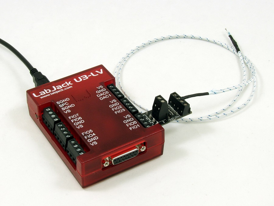
Tutorial - Type K with a U3 & LJTick-InAmp (2 or 3)
1. Connect the LJTick-InAmp
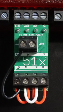
There are three gain options on the LJTick-InAmp 3: 11x, 51x, and 201x. These ranges are also select-able on the LJTick-InAmp2.
Here are their ranges and resolution:
11x: -200°C to 1250°C, Step Size = 1.3 °C (Best for Max Range)
51x: -200°C to 600°C, Step Size = 0.26 °C (Best for Max Precision)
201x: -150°C to 150°C, Step Size = 0.07 °C (Not Recommended)
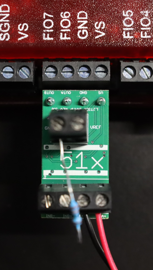
Connect the LJTick-InAmp to the FIO6/7 block of the LabJack U3.
2. Initial Testing
Start with a quick test to confirm the expected noise and offset. Use wires on the LJTick-InAmp to jumper:
-
INA+ to INA-
-
INA- to INB+
-
INB+ to INB-
-
INB- to GND
Run LJControlPanel, find and select the U3, and open the test panel.
Click the radio buttons to set FIO6-FIO7 to AIN, and their name will change to AIN6-AIN7 and you will start to see voltage readings.
They should both read ~1.25 volts.
Lastly check the bottom-right of the window, to ensure that the reading from the internal temperature sensor is reasonable.
If the U3 is at room temperature, you should see ~300 °K
3. Logger Setup
The easiest way to begin logging thermocouple temperature is with our free Windows logging software LJLogUD.
Close LJControlPanel and open LJLogUD.
By default it will read values in the first 4 rows.
+Ch is set to 0-15 in each row, -Ch is set to 199 in all rows, and Resolution and SettlingFactor are both 0. Range will be LJ_rgBIP10V in all rows, but this configuration does not apply to the U3.
Set +Ch in row 1 (the second row) to 6. Set +Ch in row 2 (the third row) to 7.
You should now see the ~0.4V reading from AIN6 and AIN7. Watch the readings from each channel to get a feel for the noise level, and confirm that it matches the information from Appendix B of the LJTick-InAmp 3 datasheet, which shows ~0.0012 volts noise-free and ~0.0003 volts effective/RMS.
The scaling equation variables are a - p corresponding to row0 - row15. For example, row4 corresponds to scaling variable e. The scaling equation described above should be adjusted accordingly if you are applying it to channels beyond row0 and row1.
4. Thermocouple Setup
Remove the jumper wires and connect one thermocouple with the positive to INA+ and the negative to INA-. Also connect a 100kΩ resistor from INA- to GND and pull on both wires going into INA- to make sure both are clamped securely.
This setup will still work with a jumper wire rather than a resistor, but you will be at risk of creating a ground loop.
Now some basic tests to see if your thermocouple is working right:
If the remote end of the thermocouple is at the same temperature as the InAmp/LabJack, the thermocouple will not generate any voltage and AIN6 should see ~1.25V.
Note this voltage as the offset for this row, and put it in a temporary scaling equation. Say the offset you see is 1.251 volts, then the scaling equation would be:
y=b-1.251

Now the scaled reading should be very close to 0.0. Put your fingers on the remote end of the thermocouple to warm it up. You should see the voltage increase by roughly 2 mV per °C (51 * 40 μV/°C) or 8 mV per °C (201 * 40 μV/°C) that the remote end is warmer than the LJTick-InAmp end.
5. Internal Temperature Sensor Measurement
Before you can convert the thermocouple voltage to temperature, you must set up the cold junction reading.
In row 0 (the first row) of LJLogUD, set +Ch to 30 which is the internal temperature sensor and returns degrees Kelvin on the U3.
If the U3 is at room temperature, you should see ~298 in the Voltage column for row 0.
6. Scaling Equation Setup
To see the internal temperature sensor readings in °C or °F change the Scaling Equation column of row 0 as follows:
y=a // °K
y=a-273.15 // °C
y=(1.8*a)-459.67 // °F
Now lets change the scaling equation for row 1 (AIN6), so that instead of showing the raw thermocouple voltage it converts it to temperature. See the Scaling Equations description in the LJLogUD/LJLogM documentation. The equation you want in this case is:
y=TCVoltsToTemp[K:(b-1.25)/51:a]-0 // °K
y=TCVoltsToTemp[K:(b-1.25)/51:a]-273.15 // °C
y=1.8*(TCVoltsToTemp[K:(b-1.25)/51:a])-459.67 // °F
... where K means Type K thermocouple, (b-1.25)/51 means the thermocouple voltage is the raw voltage from the 2nd row minus the ~1.25 offset divided by the LJTick-InAmp gain of x51, and a means the raw value from the 1st row is CJ temp in °K. The TCVoltsToTemp function supports B, E, J, K, N, R, S and T type thermocouples.
Connect a thermocouple to the other LJTick-InAmp channel in a similar manner, with a resistor or wire to GND. This should be FIO7/AIN7 and set up in the third row (Row 2). The scaling equation has the same form as previously described. Note that the variable for raw voltage from row 2 is c rather than b:
y=TCVoltsToTemp[K:(c-1.25)/51:a]
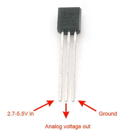
7. LM34 CJC Setup
You may have noticed that your internal temperature sensor is quite inaccurate (±5°C). To fix this, we’ll use an LJM34CAZ for cold junction temperature, rather than the internal sensor. Bend the leads as needed and connect the LM34CAZ directly to FIO4/VS/GND. Watch for correct polarity, as the diagram of the TO-92 package on the LM34 datasheet is showing the bottom view. The image below shows the typical LM34 connections:
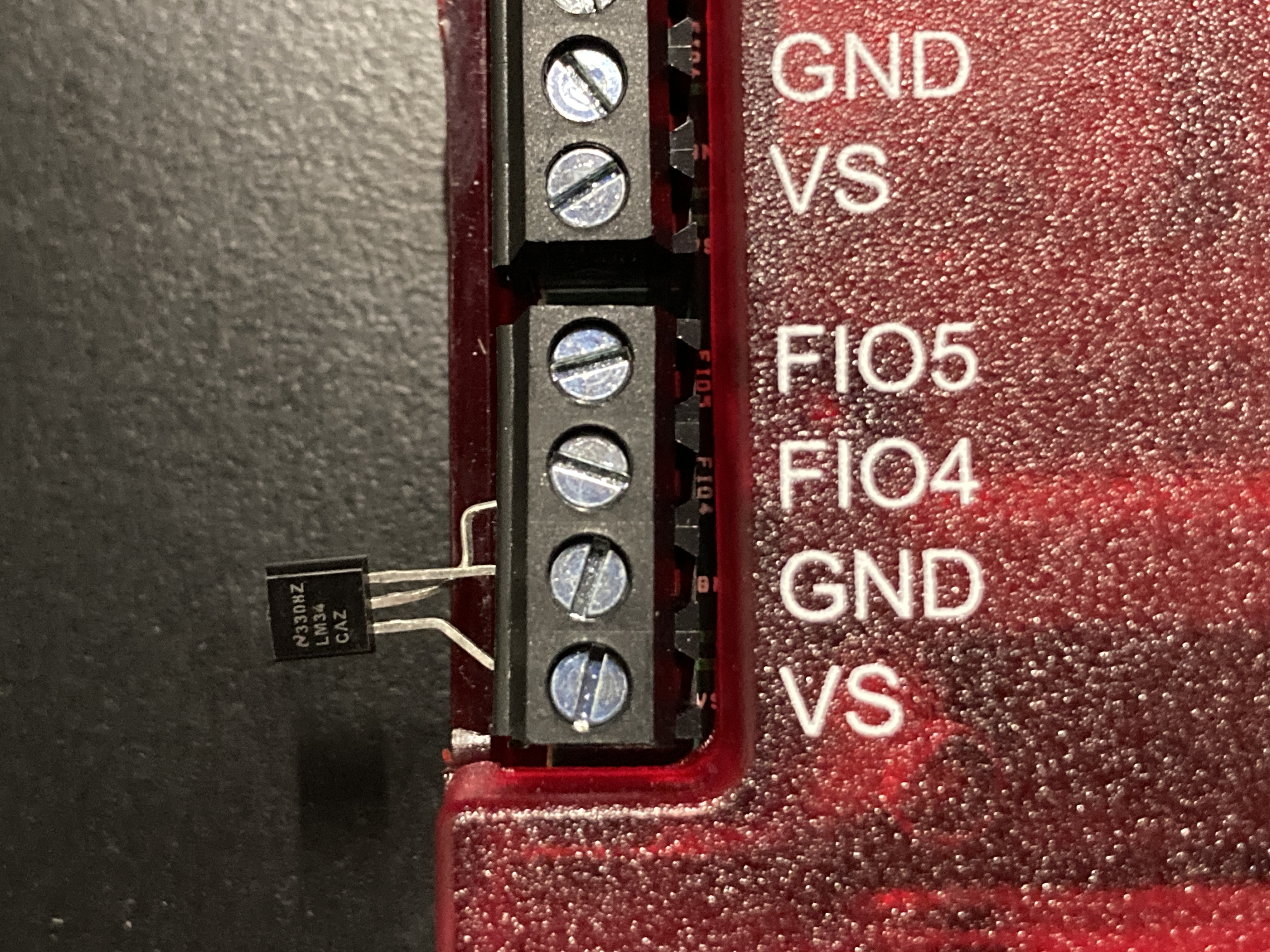
In row 0 (the first row) of LJLogUD, set +Ch to 4.
You should now see a voltage of around 0.7 if the LM34 is at room temperature.
8. LM34 CJC Scaling Equations
With the LM34 set up, you must now convert the raw voltage reading to temperature. Use the following in the Scaling Equations column of row 0 where the LM34 was set up:
y=100*a // LM34 voltage to °F
y=55.56*a - 17.78 // /LM34 voltage to °C
y=55.56*a + 255.37 // /LM34 voltage to °K
Next, you need to change all the scaling equations for the thermocouple rows. The last parameter in the TCVoltsToTemp function is cold junction temperature in Kelvin. Since the raw value from the internal temp sensor was in K you could simply use a in all the scaling equations, but now the raw value from row 0 is in volts. As such, you need to add scaling for the last (CJCTemp) parameter. The equations should look like:
y=TCVoltsToTemp[K:(b-1.25)/51:(55.56*a)+255.37]
y=TCVoltsToTemp[K:(c-1.25)/51:(55.56*a)+255.37]
You should now be able to measure temperature with much greater accuracy!